
Owner's manual

www.vishay.com For technical questions, contact: indmodules@vishay.com
Document Number: 94630
8 Revision: 05-Aug-09
VSK.41.., VSK.56.. Series
Vishay High Power Products
ADD-A-PAK Generation VII Power Modules
Thyristor/Diode and Thyristor/Thyristor, 45 A/60 A
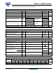
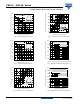
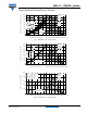
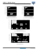
Fig. 19 - On-State Voltage Drop Characteristics Fig. 20 - On-State Voltage Drop Characteristics
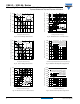
Fig. 21 - Thermal Impedance Z
thJC
Characteristics
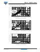
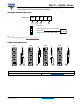
Fig. 22 - Gate Characteristics
Instantaneous on-state voltage (V)
Instantaneous on-state current (A)
0.5 1.0 1.5 2.0 2.5 3.0 3.5 4.0 4.5 5.0
1
10
100
1000
Tj = 25°C
Tj = 125°C
VSK. 41 Series
Per leg
Instantaneous on-state voltage (V)
Instantaneous on-state current (A)
0.5 1.0 1.5 2.0 2.5 3.0 3.5 4.0 4.5 5.0
1
10
100
1000
Tj = 25°C
Tj = 125°C
VSK. 56 Series
Per leg
Square wave pulse duration (s)
Transient thermal impedance Z
thJC
(°C/W)
0.001 0.01 0.1 1 10
0.01
0.1
1
Steady state value
RthJC = 0.44 °C/W
RthJC = 0.35 °C/W
(DC operation)
Per leg
VSK.41 Series
VSK.56 Series
0.1
1
10
100
0.001 0.01 0.1 1 10 100 1000
(b)
(a)
Rectangular gate pulse
(4)
(3)
(2) (1)
(1) PGM = 100 W, t p = 500 µs
(2) PGM = 50 W, tp = 1 ms
(3) PGM = 20 W, tp = 25 ms
(4) PGM = 10 W, tp = 5 ms
TJ = - 4 0 ° C
TJ = 2 5 ° C
T
J = 125 °C
a)Recommended load line for
b)Rec ommended loa d line for
VGD
IGD
Fr e q u e n c y Li m i t e d b y PG ( A V )
rated di/dt: 20 V, 30 ohms
t r = 0.5 µs, t p >= 6 µs
<= 30% ra ted d i/ dt : 20 V, 65 ohm s
tr = 1 µs, tp >= 6 µs
IRK.41../ .56.. Se rie s
Instantaneous gate voltage (V)
Instantaneous gate current (A)
VSK.