
Owner's manual

Document Number: 94630 For technical questions, contact: indmodules@vishay.com
www.vishay.com
Revision: 05-Aug-09 5
VSK.41.., VSK.56.. Series
ADD-A-PAK Generation VII Power Modules
Thyristor/Diode and Thyristor/Thyristor, 45 A/60 A
Vishay High Power Products
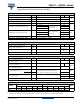
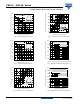
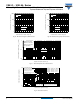
Fig. 7 - On-State Power Loss Characteristics
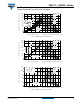
Fig. 8 - On-State Power Loss Characteristics
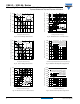
Fig. 9 - On-State Power Loss Characteristics
Total RMS output current (A)
Maximum total on-state power loss (W)
Maximum allowable ambient temperature (°C)
0 20 40 60 80 100 120 140
RthSA = 0.1 °C/W
0.3 °C/W
0.5 °C/W
0.7 °C/W
1 °C/W
1.5 °C/W
2 °C/W
3 °C/W
5 °C/W
0 20406080100
0
20
40
60
80
100
120
140
160
180°
120°
90°
60°
30°
VSK.41 Series
Per module
Tj = 125°C
Total output current (A)
Maximum total power loss (W)
Maximum allowable ambient temperature (°C)
0 20 40 60 80 100 120 140
RthSA = 0.1 °C/W
0.2 °C/W
0.3 °C/W
0.5 °C/W
0.7 °C/W
1 °C/W
1.5 °C/W
020406080100
0
50
100
150
200
250
300
350
180°
(sine)
180°
(rect)
2 x VSK.41 Series
single phase bridge connected
Tj = 125°C
∼
Total output current (A)
Maximum allowable ambient temperature (°C)
Maximum total power loss (W)
0 20 40 60 80 100 120 140
RthSA = 0.1 °C/W
0.2 °C/W
0.3 °C/W
0.5 °C/W
0.7 °C/W
1 °C/W
0 20406080100120140
0
100
200
300
400
500
120°
(rect)
3 x VSK.41 Series
three phase bridge connected
Tj = 125°C