6121 Baker Road, Suite 108 Minnetonka, MN 55345 Phone (952) 933-6190 Fax (952) 933-6223 1-800-274-4284 www.chtechnology.com Thank you for downloading this document from C&H Technology, Inc. Please contact the C&H Technology team for the following questions - Technical Application Assembly Availability Pricing Phone – 1-800-274-4284 E-Mail – sales@chtechnology.com www.chtechnology.com - SPECIALISTS IN POWER ELECTRONIC COMPONENTS AND ASSEMBLIES - www.chtechnology.
VSK.56..PbF/VSK.71..
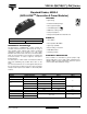
VSK.56..PbF/VSK.71..PbF Series Vishay High Power Products Standard Diodes, 60/80 A (ADD-A-PAKTM Generation 5 Power Modules) ELECTRICAL SPECIFICATIONS VOLTAGE RATINGS TYPE NUMBER VOLTAGE CODE VRRM, MAXIMUM REPETITIVE PEAK REVERSE VOLTAGE V VRSM, MAXIMUM NON-REPETITIVE PEAK REVERSE VOLTAGE V 04 400 500 06 600 700 VSK.56/.
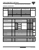
VSK.56..PbF/VSK.71..PbF Series Standard Diodes, 60/80 A Vishay High Power Products TM (ADD-A-PAK Generation 5 Power Modules) THERMAL AND MECHANICAL SPECIFICATIONS PARAMETER SYMBOL Junction and storage temperature range TEST CONDITIONS VSK.56 TJ, TStg VSK.71 - 40 to 150 Maximum thermal resistance, junction to case per junction RthJC DC operation Typical thermal resistance, case to heatsink RthCS Mounting surface flat, smooth and greased 0.5 UNITS °C 0.4 K/W 0.
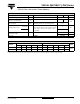
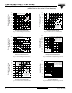
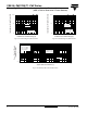
VSK.56..PbF/VSK.71..PbF Series Standard Diodes, 60/80 A (ADD-A-PAKTM Generation 5 Power Modules) Vishay High Power Products 120 VSK.56.. Series RthJC (DC) = 0.5 K/W 140 Maximum Average Forward Power Loss (W) Maximum Allowable Case Tmperature (°C) 150 130 Ø Conduction angle 120 110 100 90° 60° 30° 90 0 10 20 30 40 120° 180° 50 DC 180° 120° 90° 60° 30° 100 80 60 Ø 40 Conduction period 20 VSK.56.. Series Per junction TJ = 150 °C 0 60 0 70 Average Forward Current (A) Fig.
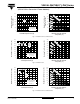
VSK.56..PbF/VSK.71..PbF Series 120 120 100 100 80 180° (Sine) Maximum Total Forward Power Loss (W) Maximum Total Forward Power Loss (W) Standard Diodes, 60/80 A Vishay High Power Products TM (ADD-A-PAK Generation 5 Power Modules) DC 60 40 VSK.56.. Series Per junction TJ = 150 °C 20 0.7 1.0 80 R th K/ SA 0. 5 K/W 40 1.5 K/W 2.0 K/W 3.0 K /W 20 7.
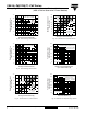
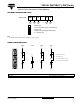
VSK.56..PbF/VSK.71..PbF Series Standard Diodes, 60/80 A (ADD-A-PAKTM Generation 5 Power Modules) Vishay High Power Products 160 VSK.71.. Series RthJC (DC) = 0.4 K/W 140 130 Maximum Average Forward Power Loss (W) Maximum Allowable Case Temperature (°C) 150 Ø Conduction angle 120 110 30° 100 60° 90° 120° DC 180° 120° 90° 60° 30° 140 120 100 RMS limit 80 Ø 60 Conduction period 40 VSK.71..
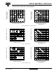
VSK.56..PbF/VSK.71..PbF Series 160 160 140 140 Maximum Total Forward Power Loss (W) Maximum Total Forward Power Loss (W) Standard Diodes, 60/80 A Vishay High Power Products TM (ADD-A-PAK Generation 5 Power Modules) 120 180° (Sine) 100 DC 80 60 40 VSK.71.. Series Per junction TJ = 150 °C 20 R th SA = 120 100 1.0 K/W 80 1.5 K/W 2.0 K/W 3.0 K /W 5.0 K/W 60 40 0. 4 0.
VSK.56..PbF/VSK.71..PbF Series Standard Diodes, 60/80 A (ADD-A-PAKTM Generation 5 Power Modules) 1000 100 Instantaneous Forward Current (A) Instantaneous Forward Current (A) Vishay High Power Products TJ = 25 °C TJ = 150 °C VSK.56.. Series Per junction 10 0.5 1.0 1.5 2.0 2.5 3.0 1000 TJ = 25 °C 100 TJ = 150 °C VSK.71.. Series Per junction 10 0 3.5 0.5 1.0 1.5 2.0 2.5 3.0 3.5 Instantaneous Forward Voltage (V) Instantaneous Forward Voltage (V) Fig.
VSK.56..PbF/VSK.71..PbF Series Standard Diodes, 60/80 A Vishay High Power Products TM (ADD-A-PAK Generation 5 Power Modules) ORDERING INFORMATION TABLE Device code VSK D 71 1 2 3 / 16 P 4 5 1 - Module type 2 - Circuit configuration (see end of datasheet) 3 - Current code 4 - Voltage code (see Voltage Ratings table) 5 - P = Lead (Pb)-free Note • To order the optional hardware go to www.vishay.com/doc?95172 CIRCUIT CONFIGURATION VSKD... VSKE... (1) ~ VSKJ... (1) - VSKC...