6121 Baker Road, Suite 108 Minnetonka, MN 55345 Phone (952) 933-6190 Fax (952) 933-6223 1-800-274-4284 www.chtechnology.com Thank you for downloading this document from C&H Technology, Inc. Please contact the C&H Technology team for the following questions - Technical Application Assembly Availability Pricing Phone – 1-800-274-4284 E-Mail – sales@chtechnology.com www.chtechnology.com - SPECIALISTS IN POWER ELECTRONIC COMPONENTS AND ASSEMBLIES - www.chtechnology.
VSK.166, .196, .236..
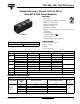
VSK.166, .196, .236..PbF Series Vishay High Power Products Standard Recovery Diodes, 165 A to 230 A (New INT-A-PAK Power Modules) FORWARD CONDUCTION PARAMETER SYMBOL Maximum average on-state current at case temperature Maximum RMS on-state current IF(AV) TEST CONDITIONS 180° conduction, half sine wave IF(RMS) t = 10 ms Maximum peak, one-cycle on-state, non-repetitive surge current IFSM No voltage reapplied t = 8.3 ms t = 10 ms 100 % VRRM reapplied t = 8.
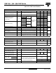
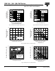
VSK.166, .196, .236..PbF Series Standard Recovery Diodes, 165 A to 230 A (New INT-A-PAK Power Modules) Vishay High Power Products ΔR CONDUCTION PER JUNCTION SINUSOIDAL CONDUCTION AT TJ MAXIMUM DEVICES 180° RECTANGULAR CONDUCTION AT TJ MAXIMUM 120° 90° 60° 30° 180° 120° 90° 60° UNITS 30° VSK.166 0.025 0.03 0.038 0.055 0.089 0.018 0.031 0.041 0.057 0.089 VSK.196 0.016 0.019 0.024 0.034 0.053 0.012 0.02 0.026 0.035 0.054 VSK.236 0.009 0.010 0.014 0.018 0.025 0.008 0.
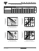
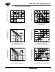
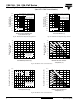
VSK.166, .196, .236..PbF Series Vishay High Power Products Standard Recovery Diodes, 165 A to 230 A (New INT-A-PAK Power Modules) At any rated load condition and with rated VRRM applied following surge. Initial TJ = 150 °C at 60 Hz 0.0083 s at 50 Hz 0.0100 s Peak Half Sine Wave Forward Current (A) 3500 3000 2500 2000 4000 1500 3000 2500 2000 1500 1000 VSK.166.. Series VSK.166.. Series 500 1000 1 10 Fig.
VSK.166, .196, .236..PbF Series Standard Recovery Diodes, 165 A to 230 A (New INT-A-PAK Power Modules) 3 x VSK.166.. Series Three phase bridge Connected TJ = 150 °C 400 200 0.1 1000 800 K/W 0.1 R -Δ 600 K/ W W K/ 800 06 02 0. 1000 0. 1200 = 120° (Rect) SA ~ 1200 1400 R th 1400 W K/ Maximum Total Power Loss (W) 1600 04 0. Maximum Total Power Loss (W) 1600 Vishay High Power Products 6K 600 0.25 400 /W K/W 0.
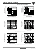
VSK.166, .196, .236..PbF Series Vishay High Power Products Standard Recovery Diodes, 165 A to 230 A (New INT-A-PAK Power Modules) At any rated load condition and with rated VRRM applied following surge. Initial TJ = 150 °C at 60 Hz 0.0083 s at 50 Hz 0.0100 s Peal Half Sine Wave Forward Current (A) 4000 3500 3000 2500 2000 1500 5000 VSK.196.. Series 10 3500 3000 2500 2000 W R -Δ Maximum Total Forward Power Loss (W) W K/ 0.7 K/W .12 =0 200 SA 50 0.5 K/W K/ W W VSK.196..
VSK.166, .196, .236..PbF Series Standard Recovery Diodes, 165 A to 230 A (New INT-A-PAK Power Modules) 1800 1600 600 3 x VSK.196.. Series Three phase bridge Connected TJ = 150 °C 400 200 K/ W 8K /W 1000 0.1 800 0.1 600 0.25 400 0.4 K R -Δ 800 0.0 1200 W K/ 1000 06 12 0. 1200 0. = - 1600 1400 SA 1400 120° (Rect) W K/ ~ R th + 04 0.
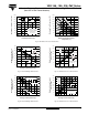
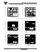
VSK.166, .196, .236..PbF Series Vishay High Power Products Standard Recovery Diodes, 165 A to 230 A (New INT-A-PAK Power Modules) At any rated load condition and with rated VRRM applied following surge. Initial TJ = 150 °C at 60 Hz 0.0083 s at 50 Hz 0.0100 s Peak Half Sine Wave Forward Curren (A) 4500 4000 3500 3000 2500 2000 5500 VSK.236.. Series 4500 4000 3500 3000 2500 2000 VSK.236.. Series 1500 1000 1500 1 10 0.01 100 Number of Equal Amplitude Half Cycle Current Pulse (A) Fig.
VSK.166, .196, .236..PbF Series Standard Recovery Diodes, 165 A to 230 A (New INT-A-PAK Power Modules) 2500 Maximum Total Power Loss (W) 2500 Maximum Total Power Loss (W) Vishay High Power Products + ~ 2000 - 120° (Rect) 1500 1000 3 x VSK.236.. Series Three phase bridge Connected TJ = 150 °C 500 0 R 2000 th SA 0.0 4K 0.0 1500 = 0. 02 /W 6K K/ W /W 0.1 1000 -Δ R K/W 0.16 K/W 0.3 K/W 500 0.
VSK.166, .196, .236..PbF Series Vishay High Power Products Standard Recovery Diodes, 165 A to 230 A 1 Steady state value (DC operation) 0.1 VSK.196.. Series 0.01 0.01 0.1 1 Instantaneous On-State Current (A) Instantaneous On-State Current (A) (New INT-A-PAK Power Modules) 1.0 Steady state value (DC operation) 0.1 VSK.236.. Series 0.01 0.01 10 0.1 1.0 10 Square Wave Pulse Duration (s) Square Wave Pulse Duration (s) Fig. 32 - Thermal Impedance ZthJC Characteristics Fig.
Outline Dimensions Vishay High Power Products INT-A-PAK DBC 28 (1.10) 9 (0.33) 30 (1.18) DIMENSIONS in millimeters (inches) Ø 6.5 (Ø 0.25) 80 (3.15) 23 (0.91) 7 6 5 4 14.5 23 (0.91) (0.57) 35 (1.38) 17 (0.67) 1 2 3 66 (2.60) 37 (1.44) 3 screws M6 x 10 94 (3.70) Document Number: 95254 Revision: 11-Dec-07 For technical questions concerning discrete products, contact: diodes-tech@vishay.com For technical questions concerning module products, contact: ind-modules@vishay.com www.vishay.