
Manual

Document Number: 93842 For technical questions, contact: die-wafer@vishay.com
www.vishay.com
Revision: 28-Mar-08 1
Phase Control Thyristors
VS343SG12H
Vishay High Power Products
FEATURES
• 100 % tested at probe
• Solderable SCR
• Probed die in chip carrier
Note
(1)
Nitrogen flow on die edge
PRODUCT SUMMARY
Junction size Square 343 mils
Wafer size 4"
V
RRM
/V
DRM
class 1200 V
Passivation process Glassivated MESA
Reference Vishay HPP
packaged part
N/a
RoHS
COMPLIANT
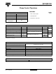
MAJOR RATINGS AND CHARACTERISTICS
PARAMETER SYMBOL TEST CONDITIONS VALUES UNITS
Typical on-state voltage V
TM
T
J
= 25 °C, I
T
= 25 A 1.2
V
Maximum repetitive reverse/forward voltage V
RRM
/V
DRM
(1)
T
J
= 25 °C, I
RRM
/I
DRM
= 100 µA 1200
Required DC gate current to trigger I
GT
T
J
= 25 °C, anode supply = 6 V, resistive load
5 to 100 mA
Maximum required DC gate voltage to trigger V
GT
2V
Holding current Range I
H
Anode supply = 6 V, resistive load
5 to 200
mA
Maximum latching current I
L
400
MECHANICAL DATA
Nominal back metal composition (thickness)
Cr-Ni-Ag (1 kÅ - 4 kÅ - 6 kÅ)
Nominal front metal composition (thickness)
Chip dimensions 340 x 340 mils - see dimensions (link at the end of datasheet)
Wafer diameter 100 mm, with standard < 110 > flat
Wafer thickness 330 µm ± 10 µm
Maximum width of sawing line 130 µm
Reject ink dot size Ø 0.25 mm minimum
Ink dot location See dimensions (link at the end of datasheet)
Recommended storage environment Storage in original container, in desiccated nitrogen, with no contamination
LINKS TO RELATED DOCUMENTS
Dimensions http://www.vishay.com/doc?95129