
Instruction Manual

VS-T20HF220
www.vishay.com
Vishay Semiconductors
Revision: 24-Apr-12
3
Document Number: 94709
For technical questions within your region: DiodesAmericas@vishay.com
, DiodesAsia@vishay.com, DiodesEurope@vishay.com
THIS DOCUMENT IS SUBJECT TO CHANGE WITHOUT NOTICE. THE PRODUCTS DESCRIBED HEREIN AND THIS DOCUMENT
ARE SUBJECT TO SPECIFIC DISCLAIMERS, SET FORTH AT www.vishay.com/doc?91000
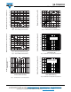
Fig. 1 - Current Ratings Characteristics
Fig. 2 - Current Ratings Characteristics
Fig. 3 - Forward Power Loss Characteristics
Fig. 4 - Forward Power Loss Characteristics
Fig. 5 - Maximum Non-Repetitive Surge Current
Fig. 6 - Maximum Non-Repetitive Surge Current
Maximum Allowable Case Temperature (°C)
I
F(AV)
-
Average
Forward Current (A)
100
110
120
130
140
150
160
50
60
70
80
90
0102030
30°
60°
90°
120°
180°
Maximum Allowable Case Temperature (°C)
I
F(AV)
-
Average
Forward Current (A)
100
110
120
130
140
150
160
60
70
80
90
0102030
30°
60°
90°
120°
180°
DC
Maximum Forward Power Loss
Characteristics
Anode
Forward Current (A)
0102030405060
30°
60°
90°
120°
180°
RMS limit
0
50
75
25
40
50
60
70
80
90
100
0
10
20
30
0 10 20 30 40 50 60 70 80
30°
60°
90°
120°
180°
DC
RM
S limit
Maximum Forward Power Loss (W)
Anode
Forward Current (A)
100
150
200
250
300
350
400
450
500
110100
Peak Half Sine Wave Forward Current (A)
Number Of Equal Amplitude Half Cycle
Current Pulses (N)
at 60 Hz 0.0083 s
at 50 Hz 0.0100 s
20
120
220
320
420
520
620
0.01 0.1 1
No Voltage Reapplied
Rated V
RRM
Reapplied
Peak Half Sine Wave Forward Current (A)
Pulse Train Duration (s)