
Instruction Manual

VS-T20HF220
www.vishay.com
Vishay Semiconductors
Revision: 24-Apr-12
2
Document Number: 94709
For technical questions within your region: DiodesAmericas@vishay.com
, DiodesAsia@vishay.com, DiodesEurope@vishay.com
THIS DOCUMENT IS SUBJECT TO CHANGE WITHOUT NOTICE. THE PRODUCTS DESCRIBED HEREIN AND THIS DOCUMENT
ARE SUBJECT TO SPECIFIC DISCLAIMERS, SET FORTH AT www.vishay.com/doc?91000
Note
(1)
A mounting compound is recommended and the torque should be rechecked after a period of about 3 hours to allow for the spread of the
compound
Note
• Table shows the increment of thermal resistance R
thJC
when devices operate at different conduction angles than DC
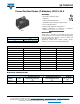
FORWARD CONDUCTION
PARAMETER SYMBOL TEST CONDITIONS T20HF UNITS
Maximum average forward current
at case temperature
I
F(AV)
180° conduction, half sine wave
20 A
85 °C
Maximum RMS forward current I
F(RMS)
31 A
Maximum peak, one-cycle
forward, non-repetitive
surge current
I
FSM
t = 10 ms
No voltage
reapplied
Sinusoidal
half wave,
initial T
J
=
T
J
maximum
450
A
t = 8.3 ms 470
t = 10 ms
100 % V
RRM
reapplied
380
t = 8.3 ms 400
Maximum I
2
t for fusing I
2
t
t = 10 ms
No voltage
reapplied
1015
A
2
s
t = 8.3 ms 920
t = 10 ms
100 % V
RRM
reapplied
715
t = 8.3 ms 650
Maximum I
2
t for fusing I
2
t t = 0.1 ms to 10 ms, no voltage reapplied 10 125 A
2
s
Low level value of
threshold voltage
V
F(TO)1
(16.7 % x x I
F(AV)
< I < x I
F(AV)
),
T
J
maximum
0.77
V
High level value of
threshold voltage
V
F(TO)2
(I > x I
F(AV)
), T
J
maximum 0.89
Low level value of
forward slope resistance
r
f1
(16.7 % x x I
F(AV)
< I < x I
F(AV)
),
T
J
maximum
8.5
m
High level value of
forward slope resistance
r
f2
(I > x I
F(AV)
), T
J
maximum 6.7
Maximum forward voltage drop V
FM
I
FM
= 60 A, T
J
= 25 °C,
t
p
= 400 μs square pulse
Average power = V
F(TO)
x I
F(AV)
+ r
f
x (I
F(RMS)
)
2
1.50 V
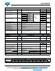
BLOCKING
PARAMETER SYMBOL TEST CONDITIONS T20HF UNITS
Maximum peak reverse
leakage current
I
RRM
T
J
= 150 °C 18 mA
RMS isolation voltage V
ISOL
50 Hz, circuit to base, all terminals shorted
T
J
= 25 °C, t = 1 s
3500 V
THERMAL AND MECHANICAL SPECIFICATIONS
PARAMETER SYMBOL TEST CONDITIONS
VALUES
UNITS
T20HF
Maximum junction operating
and storage temperature range
T
J
, T
Stg
- 40 to 150 °C
Maximum thermal resistance,
junction to case per junction
R
thJC
DC operation 2.53
K/W
Maximum thermal resistance,
case to heatsink
R
thCS
Mounting surface smooth, flat
and greased
0.2
Mounting torque,
± 10 %
to heatsink
Non-lubricated
threads
M3.5 mounting screws
(1)
1.3 ± 10 %
Nm
terminals M5 screw terminals 3 ± 10 %
Approximate weight See dimensions - link at the end of datasheet 54 g
Case style T-module (D-55)
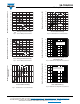
R CONDUCTION PER JUNCTION
DEVICES
SINUSOIDAL CONDUCTION AT T
J
MAXIMUM RECTANGULAR CONDUCTION AT T
J
MAXIMUM
UNITS
180° 120° 90° 60° 30° 180° 120° 90° 60° 30°
T20HF... 0.29 0.34 0.43 0.64 1.10 0.20 0.35 0.47 0.67 1.11 K/W