6121 Baker Road, Suite 108 Minnetonka, MN 55345 Phone (952) 933-6190 Fax (952) 933-6223 1-800-274-4284 www.chtechnology.com Thank you for downloading this document from C&H Technology, Inc. Please contact the C&H Technology team for the following questions - Technical Application Assembly Availability Pricing Phone – 1-800-274-4284 E-Mail – sales@chtechnology.com www.chtechnology.com - SPECIALISTS IN POWER ELECTRONIC COMPONENTS AND ASSEMBLIES - www.chtechnology.
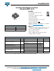
VS-GB90SA120U www.vishay.com Vishay Semiconductors Insulated Gate Bipolar Transistor (Ultrafast IGBT), 90 A FEATURES • NPT Generation V IGBT technology • Square RBSOA • Positive VCE(on) temperature coefficient • Fully isolated package • Speed 8 kHz to 60 kHz SOT-227 • Very low internal inductance ( 5 nH typical) • Industry standard outline • UL approved file E78996 • Material categorization: For definitions of compliance please see www.vishay.
VS-GB90SA120U www.vishay.com Vishay Semiconductors ELECTRICAL SPECIFICATIONS (TJ = 25 °C unless otherwise specified) PARAMETER SYMBOL Collector to emitter breakdown voltage VBR(CES) Collector to emitter voltage VCE(on) Gate threshold voltage VGE(th) Temperature coefficient of threshold voltage VGE(th)/TJ Collector to emitter leakage current ICES Gate to emitter leakage current IGES TEST CONDITIONS MIN. TYP. MAX. VGE = 0 V, IC = 250 μA 1200 - - VGE = 15 V, IC = 75 A - 3.3 3.
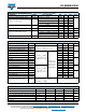
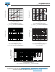
VS-GB90SA120U 160 140 120 DC 100 80 60 40 20 0 20 60 80 100 120 140 160 100 TJ = 150 °C 10 1 TJ = 125 °C 0.1 0.01 TJ = 25 °C 0.001 0.0001 0 200 400 600 800 1000 1200 IC - Continuous Collector Current (A) VCES - Collector-to-Emitter Voltage (V) Fig. 1 - Maximum DC IGBT Collector Current vs. Case Temperature Fig. 4 - Typical IGBT Zero Gate Voltage Collector Current 200 6 VGE = 15 V 150 TJ = 125 °C 100 TJ = 150 °C TJ = 25 °C 50 0 TJ = 25 °C 5.5 5 4.5 4 TJ = 125 °C 3.5 3 2.
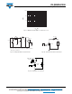
VS-GB90SA120U www.vishay.com Vishay Semiconductors 5 14 3.5 3 2.5 2 Eon 12 Eoff 4 Energy Losses (mJ) Switching Energy (mJ) 4.5 Eon 1.5 1 10 Eoff 8 6 4 2 0.5 0 0 10 20 30 40 50 60 70 80 90 0 100 10 20 30 40 50 Rg (Ω) IC - Collector Current (A) Fig. 7 - Typical IGBT Energy Losses vs. IC TJ = 125 °C, L = 500 μH, VCC = 600 V, Rg = 5 , VGE = 15 V, Diode used HFA16PB120 Fig. 9 - Typical IGBT Energy Loss vs.
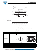
VS-GB90SA120U www.vishay.com Vishay Semiconductors 1000 IC (A) 100 10 1 10 100 1000 10 000 VCE (V) Fig. 12 - IGBT Reverse Bias SOA, TJ = 150 °C, VGE = 15 V R= L D.U.T. VCC ICM VC * 50 V 1000 V D.U.T. 1 2 + -V CC Rg * Driver same type as D.U.T.; VC = 80 % of Vce(max.) * Note: Due to the 50 V power supply, pulse width and inductor will increase to obtain Id Fig. 13a - Clamped Inductive Load Test Circuit Fig. 13b - Pulsed Collector Current Test Circuit Diode clamp/ D.U.T. L - + -5V D.U.
VS-GB90SA120U www.vishay.com Vishay Semiconductors 1 2 90 % 10 % 3 VC 90 % td(off) 10 % 5% IC tf tr td(on) t = 5 µs Eoff Eon Ets = (Eon + Eoff) Fig.
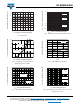
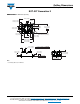
Outline Dimensions www.vishay.com Vishay Semiconductors SOT-227 Generation II DIMENSIONS in millimeters (inches) 38.30 (1.508) 37.80 (1.488) Ø 4.10 (0.161) Ø 4.30 (0.169) -A- 4 x M4 nuts 6.25 (0.246) 6.50 (0.256) 12.50 (0.492) 13.00 (0.512) 25.70 (1.012) 24.70 (0.972) -B- 7.45 (0.293) 7.60 (0.299) 14.90 (0.587) 15.20 (0.598) R full 2.10 (0.083) 2.20 (0.087) 30.50 (1.200) 29.80 (1.173) 31.50 (1.240) 32.10 (1.264) 4x 2.20 (0.087) 1.90 (0.075) 8.30 (0.327) 7.70 (0.303) 0.25 (0.
Legal Disclaimer Notice www.vishay.com Vishay Disclaimer ALL PRODUCT, PRODUCT SPECIFICATIONS AND DATA ARE SUBJECT TO CHANGE WITHOUT NOTICE TO IMPROVE RELIABILITY, FUNCTION OR DESIGN OR OTHERWISE. Vishay Intertechnology, Inc., its affiliates, agents, and employees, and all persons acting on its or their behalf (collectively, “Vishay”), disclaim any and all liability for any errors, inaccuracies or incompleteness contained in any datasheet or in any other disclosure relating to any product.