
Owner's manual

VS-GB400TH120U
www.vishay.com
Vishay Semiconductors
Revision: 06-Mar-13
1
Document Number: 94789
For technical questions within your region: DiodesAmericas@vishay.com
, DiodesAsia@vishay.com, DiodesEurope@vishay.com
THIS DOCUMENT IS SUBJECT TO CHANGE WITHOUT NOTICE. THE PRODUCTS DESCRIBED HEREIN AND THIS DOCUMENT
ARE SUBJECT TO SPECIFIC DISCLAIMERS, SET FORTH AT www.vishay.com/doc?91000
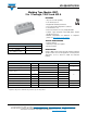
Molding Type Module IGBT,
2 in 1 Package, 1200 V and 400 A
FEATURES
• 10 μs short circuit capability
• Low switching losses
• Rugged with ultrafast performance
•V
CE(on)
with positive temperature coefficient
• Low inductance case
• Fast and soft reverse recovery antiparallel FWD
• Isolated copper baseplate using DCB (Direct Copper
Bonding) technology
• Material categorization: For definitions of compliance
please see www.vishay.com/doc?99912
TYPICAL APPLICATIONS
• Inductive heating
• Switching mode power supplies
• Electronic welder
DESCRIPTION
Vishay’s IGBT power module provides ultrafast switching
speed as well as short circuit ruggedness. It is designed for
applications such as electronic welder and inductive
heating.
Note
(1)
Repetitive rating: Pulse width limited by maximum junction temperature.
PRODUCT SUMMARY
V
CES
1200 V
I
C
at T
C
= 80 °C 400 A
V
CE(on)
(typical)
at I
C
= 400 A, T
J
= 25 °C
3.10 V
Double INT-A-PAK
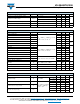
ABSOLUTE MAXIMUM RATINGS (T
C
= 25 °C unless otherwise noted)
PARAMETER SYMBOL TEST CONDITIONS MAX. UNITS
Collector to emitter voltage V
CES
1200
V
Gate to emitter voltage V
GES
± 20
Collector current I
C
T
C
= 25 °C 660
A
T
C
= 80 °C 400
Pulsed collector current I
CM
(1)
t
p
= 1 ms 800
Diode continuous forward current I
F
T
C
= 80 °C 400
Diode maximum forward current I
FM
(1)
t
p
= 1 ms 800
Maximum power dissipation P
D
T
J
= 150 °C 2660 W
Short circuit withstand time T
SC
T
J
= 125 °C 10 μs
RMS isolation voltage V
ISOL
f = 50 Hz, t = 1 min 2500 V