6121 Baker Road, Suite 108 Minnetonka, MN 55345 Phone (952) 933-6190 Fax (952) 933-6223 1-800-274-4284 www.chtechnology.com Thank you for downloading this document from C&H Technology, Inc. Please contact the C&H Technology team for the following questions - Technical Application Assembly Availability Pricing Phone – 1-800-274-4284 E-Mail – sales@chtechnology.com www.chtechnology.com - SPECIALISTS IN POWER ELECTRONIC COMPONENTS AND ASSEMBLIES - www.chtechnology.
VS-GB100TH120U www.vishay.
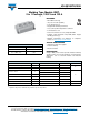
VS-GB100TH120U www.vishay.com Vishay Semiconductors IGBT ELECTRICAL SPECIFICATIONS (TC = 25 °C unless otherwise noted) PARAMETER Collector to emitter breakdown voltage Collector to emitter voltage SYMBOL V(BR)CES VCE(on) TEST CONDITIONS MIN. TYP. MAX. 1200 - - VGE = 15 V, IC = 100 A, TJ = 25 °C - 3.10 3.60 VGE = 15 V, IC = 100 A, TJ = 125 °C - 3.45 - TJ = 25 °C UNITS V VGE(th) VCE = VGE, IC = 1 mA, TJ = 25 °C 4.4 4.9 6.
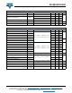
VS-GB100TH120U www.vishay.com Vishay Semiconductors DIODE ELECTRICAL SPECIFICATIONS PARAMETER SYMBOL Diode forward voltage VF Diode reverse recovery charge TEST CONDITIONS IF = 100 A Qrr Diode peak reverse recovery current Diode reverse recovery energy Irr IF = 100 A, VR = 600 V, dIF/dt = - 1900 A/μs, VGE = - 15 V MIN. TYP. MAX. TC = 25 °C - 1.82 2.22 TC = 125 °C - 1.95 - TC = 25 °C - 5.4 - TC = 125 °C - 11.
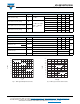
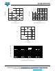
VS-GB100TH120U www.vishay.com Vishay Semiconductors 25 40 VCC = 600 V Rg = 5.6 Ω VGE = ± 15 V TJ = 125 °C 30 Eon, Eoff (mJ) Eon, Eoff (mJ) 20 15 Eon 10 VCC = 600 V IC = 100 A VGE = ± 15 V TJ = 125 °C 35 25 15 Eoff 10 Eoff 5 Eon 20 5 0 0 0 50 100 150 200 0 10 20 30 40 50 IC (A) Rg (Ω) Fig. 3 - Switching Loss vs. IC Fig. 4 - IGBT Switching Loss vs. Rg 60 250 Chip 200 IC (A) Module 150 100 Rg = 5.6 Ω VGE = ± 15 V TJ = 125 °C 50 0 0 350 700 1050 1400 VCE (V) Fig.
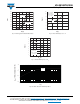
VS-GB100TH120U www.vishay.com Vishay Semiconductors 200 12 175 TJ = 25 °C 150 8 E (mJ) 125 IF (A) VCC = 600 V Rg = 5.6 Ω VGE = ± 15 V TJ = 125 °C 10 100 75 TJ = 125 °C 6 Erec 4 50 2 25 0 0 0 0.5 1.0 1.5 2.0 2.5 0 3.0 50 100 150 VF (V) IF (V) Fig. 7 - Diode Typical Forward Characteristics Fig. 8 - Diode Switching Loss vs. IF 200 8 7 Erec 6 E (mJ) 5 4 3 VCC = 600 V IF = 100 A VGE = ± 15 V TJ = 125 °C 2 1 0 0 10 20 30 40 50 60 Rg (Ω) Fig.
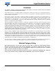
VS-GB100TH120U www.vishay.com Vishay Semiconductors CIRCUIT CONFIGURATION 6 7 1 2 3 5 4 LINKS TO RELATED DOCUMENTS Dimensions Revision: 20-Sep-12 www.vishay.com/doc?95525 Document Number: 93413 6 For technical questions within your region: DiodesAmericas@vishay.com, DiodesAsia@vishay.com, DiodesEurope@vishay.com THIS DOCUMENT IS SUBJECT TO CHANGE WITHOUT NOTICE. THE PRODUCTS DESCRIBED HEREIN AND THIS DOCUMENT ARE SUBJECT TO SPECIFIC DISCLAIMERS, SET FORTH AT www.vishay.
Legal Disclaimer Notice www.vishay.com Vishay Disclaimer ALL PRODUCT, PRODUCT SPECIFICATIONS AND DATA ARE SUBJECT TO CHANGE WITHOUT NOTICE TO IMPROVE RELIABILITY, FUNCTION OR DESIGN OR OTHERWISE. Vishay Intertechnology, Inc., its affiliates, agents, and employees, and all persons acting on its or their behalf (collectively, “Vishay”), disclaim any and all liability for any errors, inaccuracies or incompleteness contained in any datasheet or in any other disclosure relating to any product.