
Instruction Manual

VS-EMG050J60N
www.vishay.com
Vishay Semiconductors
Revision: 09-Dec-11
4
Document Number: 93495
For technical questions within your region: DiodesAmericas@vishay.com
, DiodesAsia@vishay.com, DiodesEurope@vishay.com
THIS DOCUMENT IS SUBJECT TO CHANGE WITHOUT NOTICE. THE PRODUCTS DESCRIBED HEREIN AND THIS DOCUMENT
ARE SUBJECT TO SPECIFIC DISCLAIMERS, SET FORTH AT www.vishay.com/doc?91000
Note
(1)
Mounting surface flat, smooth, and greased
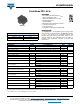
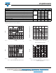
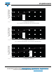
Fig. 1 - Typical PFC IGBT Output Characteristics
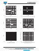
Fig. 2 - Typical PFC IGBT Output Characteristics
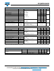
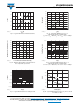
Fig. 3 - Maximum DC PFC IGBT Collector Current vs.
Case Temperature per Junction
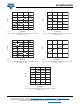
Fig. 4 - Typical PFC IGBT Collector to Emitter Voltage vs.
Junction Temperature
THERMAL AND MECHANICAL SPECIFICATIONS
PARAMETER SYMBOL MIN. TYP. MAX. UNITS
Q1 - Q2 PFC IGBT - Junction to case thermal resistance (per switch)
R
thJC
- - 0.37
°C/W
D1 - D2 AP diode - Junction to case thermal resistance (per diode) - - 4.29
D3 - D4 PFC diode - Junction to case thermal resistance (per diode) - - 1.69
Q1 - Q2 PFC IGBT - Case to sink thermal resistance (per switch)
R
thCS
(1)
-0.31-
D1 - D2 AP diode - Case to sink thermal resistance (per diode) - 3.66 -
D3 - D4 PFC diode - Case to sink thermal resistance (per diode) - 1.1 -
Mounting torque (M4) -23Nm
Weight -39- g
I
C
(A)
V
CE
(V)
0 1.5 3.01.0 2.50.5 2.0 3.5
0
93495_01
100
20
50
80
40
70
90
10
30
60
T
J
= 125 °C
T
J
= 150 °C
T
J
= 25 °C
V
GE
= 15 V
I
C
(A)
V
CE
(V)
0 1.5 2.5 3.0 3.50.5 1.0 2.0 4.0
0
93495_02
100
10
60
40
20
80
50
30
90
70
V
GE
= 8 V
V
GE
= 10 V
V
GE
= 12 V
V
GE
= 15 V
V
GE
= 18 V
T
J
= 125 °C
Allowable Case Temperature (°C)
I
C
- Continuous Collector Current (A)
80604020
100
0
100
160
0
40
60
140
80
120
20
93495_03
DC
V
CE
(V)
T
J
(°C)
10 16060 110
0.5
1.0
1.5
2.0
2.5
3.0
3.5
93495_04
4.0
100 A
50 A
27 A
V
GE
= 15 V