
Instruction Manual

VS-EMG050J60N
www.vishay.com
Vishay Semiconductors
Revision: 09-Dec-11
1
Document Number: 93495
For technical questions within your region: DiodesAmericas@vishay.com
, DiodesAsia@vishay.com, DiodesEurope@vishay.com
THIS DOCUMENT IS SUBJECT TO CHANGE WITHOUT NOTICE. THE PRODUCTS DESCRIBED HEREIN AND THIS DOCUMENT
ARE SUBJECT TO SPECIFIC DISCLAIMERS, SET FORTH AT www.vishay.com/doc?91000
Dual Mode PFC, 60 A
FEATURES
• NPT Warp2 PFC IGBT with low V
CE(ON)
• Silicon carbide PFC diode
• Antiparallel FRED Pt
®
fast recovery
• Integrated thermistor
•Square RBSOA
• Operating frequency 60 kHz to 150 kHz
• Low internal inductances
• Low switching loss
• Compliant to RoHS Directive 2002/95/EC
DESCRIPTION
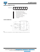
VS-EMG050J60N is an integrated solution for dual stage
PFC converter in a single package. The EMIPAK2 package
is easy to use thanks to the solderable terminals and
provides improved thermal performance thanks to the
exposed substrate. The optimized layout also helps to
minimize stray parameters, allowing for better EMI
performance.
Notes
• Absolute Maximum Ratings indicate sustained limits beyond which damage to the device may occur.
(1)
V
CC
= 400 V, V
GE
= 15 V, L = 500 μH, R
g
= 22 , T
J
= 150 °C
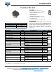
PRODUCT SUMMARY
V
CES
600 V
V
CE(ON)
typical at I
C
= 50 A 1.8 V
I
C
at T
C
= 98 °C 50 A
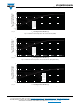
EMIPAK2
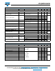
ABSOLUTE MAXIMUM RATINGS
PARAMETER SYMBOL TEST CONDITIONS MAX. UNITS
Maximum operating junction temperature T
J
150
°C
Storage temperature range T
Stg
- 40 to 125
RMS isolation voltage V
ISOL
T
J
= 25 °C, all terminals shorted, f = 50 Hz, t = 1 s 3500 V
PFC IGBT Q1 - Q2
Collector to emitter voltage V
CES
600
V
Gate to emitter voltage V
GES
20
Pulsed collector current I
CM
150
A
Clamped inductive load current I
LM
(1)
150
Continuous collector current I
C
T
C
= 25 °C 88
T
C
= 80 °C 60
Power dissipation P
D
T
C
= 25 °C 338
W
T
C
= 80 °C 189
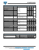
ANTIPARALLEL DIODE D1 - D2
Diode continuous forward current I
F
T
C
= 25 °C 16
AT
C
= 80 °C 11
Single pulse forward current I
FSM
10 ms sine or 6 ms rectangular pulse, T
J
= 25 °C 59
Power dissipation P
D
T
C
= 25 °C 29
W
T
C
= 80 °C 16
PFC DIODE D3 - D4
Repetitive peak reverse voltage V
RRM
600 V
Diode continuous forward current I
F
T
C
= 25 °C 25
AT
C
= 80 °C 17
Single pulse forward current I
FSM
10 ms sine or 6 ms rectangular pulse, T
J
= 25 °C 140
Power dissipation P
D
T
C
= 25 °C 74
W
T
C
= 80 °C 41