
User Manual


VS-40MT1.0P.PbF, VS-70MT1.0P.PbF, VS-100MT1.0P.PbF Series
www.vishay.com
Vishay Semiconductors
Revision: 30-Oct-13
6
Document Number: 94538
For technical questions within your region: DiodesAmericas@vishay.com
, DiodesAsia@vishay.com, DiodesEurope@vishay.com
THIS DOCUMENT IS SUBJECT TO CHANGE WITHOUT NOTICE. THE PRODUCTS DESCRIBED HEREIN AND THIS DOCUMENT
ARE SUBJECT TO SPECIFIC DISCLAIMERS, SET FORTH AT www.vishay.com/doc?91000
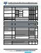
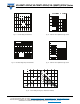
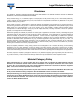
Fig. 16 - Thermal Impedance Z
thJC
Characteristics
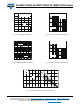
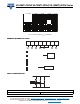
ORDERING INFORMATION TABLE
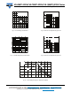
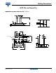
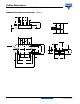
CIRCUIT CONFIGURATION
Square Wave Pulse Duration (s)
Transient Thermal Impedance Z
thJC
(K/W)
0.01
0.1
1
10
0.0001 0.001 0.01 0.1 1 1 0
Steady State Value
RthJC per junction =
1.6 K/W (40MT...P)
1.38 K/W (70MT...P
1.14 K/W (100MT...P)
DC Operation)
40MT...P
70MT...P
100MT...P
2
- Current rating code
3 - Circuit configuration code: 0 = 3-Phase rectifier bridge
4 - Essential part number
5 - Voltage code x 10 = V
RRM
(see Voltage Ratings table)
6 - Pinout code
4 = 45 A
7 = 75 A
10 = 100 A
7
- Lead (Pb)-free
A = Flat pins
B = Round pins
Device code
6
2
1
43 5 7
10 0 MT 160 P B PbF
1
VS-
- Vishay Semiconductors product
LINKS TO RELATED DOCUMENTS
Dimensions www.vishay.com/doc?95244