
User Manual

VS-40MT1.0P.PbF, VS-70MT1.0P.PbF, VS-100MT1.0P.PbF Series
www.vishay.com
Vishay Semiconductors
Revision: 30-Oct-13
2
Document Number: 94538
For technical questions within your region: DiodesAmericas@vishay.com
, DiodesAsia@vishay.com, DiodesEurope@vishay.com
THIS DOCUMENT IS SUBJECT TO CHANGE WITHOUT NOTICE. THE PRODUCTS DESCRIBED HEREIN AND THIS DOCUMENT
ARE SUBJECT TO SPECIFIC DISCLAIMERS, SET FORTH AT www.vishay.com/doc?91000
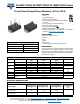
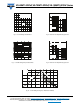
FORWARD CONDUCTION
PARAMETER SYMBOL TEST CONDITIONS 40MT 70MT 100MT UNITS
Maximum DC output current
at case temperature
I
O
120° rect. to conduction angle
45 75 100 A
100 80 80 °C
Maximum peak, one cycle
forward, non-repetitive on state
surge current
I
FSM
t = 10 ms
No voltage
reapplied
Initial
T
J
= T
J
maximum
270 380 450
t = 8.3 ms 280 398 470
t = 10 ms
100 % V
RRM
reapplied
225 320 380
t = 8.3 ms 240 335 400
Maximum I
2
t for fusing I
2
t
t = 10 ms
No voltage
reapplied
365 724 1013
A
2
s
t = 8.3 ms 325 660 920
t = 10 ms
100 % V
RRM
reapplied
253 512 600
t = 8.3 ms 240 467 665
Maximum I
2
t for fusing I
2
t t = 0.1 ms to 10 ms, no voltage reapplied 3650 7240 10 130 A
2
s
Value of threshold voltage V
F(TO)
T
J
maximum
0.78 0.82 0.75 V
Slope resistance r
t
14.8 9.5 8.1 m
Maximum forward voltage drop V
FM
T
J
= 25 °C; t
p
= 400 μs single junction
(40MT, I
pk
= 40 A) (70MT, I
pk
= 70 A) (100MT, I
pk
= 100 A)
1.45 1.45 1.51 V
INSULATION TABLE
PARAMETER SYMBOL TEST CONDITIONS 40MT 70MT 100MT UNITS
RMS insulation voltage V
INS
T
J
= 25 °C, all terminal shorted, f = 50 Hz, t = 1 s 3500 V
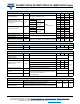
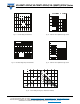
THERMAL AND MECHANICAL SPECIFICATIONS
PARAMETER SYMBOL TEST CONDITIONS 40MT 70MT 100MT UNITS
Maximum junction operating
temperature range
T
J
- 40 to 150
°C
Maximum storage
temperature range
T
Stg
- 40 to 125
Maximum thermal resistance,
junction to case
R
thJC
DC operation per module 0.27 0.23 0.19
K/W
DC operation per junction 1.6 1.38 1.14
120° rect. condunction angle per module 0.38 0.29 0.22
120° rect. condunction angle per junction 2.25 1.76 1.29
Maximum thermal resistance,
case to heatsink per module
R
thCS
Mounting surface smooth, flat and greased
Heatsink compound thermal conductivity = 0.42 W/mK
0.1
Mounting torque to heatsink
± 10 %
A mounting compound is recommended and the torque
should be rechecked after a period of 3 hours to allow
for the spread of the compound.
Lubricated threads
4Nm
Approximate weight 65 g
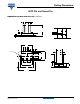
CLEARANCE AND CREEPAGE DISTANCES
PARAMETER TEST CONDITIONS MT...PA MT...PB UNITS
Clearance
External shortest distances in air between terminals
which are not internally short circuited together
10.9 12.3 mm
Creepage distance
Shortest distance along external surface of the insulating material
between terminals which are not internally short circuited together