
User Manual

Document Number: 94522 For technical questions, contact: ind-modules@vishay.com
www.vishay.com
Revision: 07-May-08 3
UFB120FA20P
Insulated Ultrafast
Rectifier Module, 120 A
Vishay High Power Products
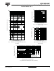
Fig. 1 - Maximum Forward Voltage Drop Characteristics
(Per Diode)
Fig. 2 - Typical Values of Reverse Current vs.
Reverse Voltage
Fig. 3 - Typical Junction Capacitance vs.
Reverse Voltage
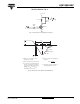
Fig. 4 - Maximum Thermal Impedance Z
thJC
(Per Diode)
Forward Voltage Drop - V
FM
(V)
Instantaneous Forward Current - I
F
(A)
1
10
100
1000
0.2 0.6 1 1.4 1.8
Tj = 150˚C
Tj = 125˚C
Tj = 25˚C
Reverse Voltage - V
R
(V)
Reverse Current - I
R
(µA)
0.001
0.01
0.1
1
10
100
050100150200
125˚C
25˚C
Tj = 150˚C
Reverse Voltage - V
R
(V)
Junction Capacitance - C
T
( p F )
100
1000
1 10 100 1000
Tj = 25˚C
t
1
, Rectangular Pulse Duration (Seconds)
Thermal Impedance Z
thJC
(°C/W)
0.01
0.1
1
10
0.001 0.01 0.1 1 10
Single Pulse
(Thermal Impedance)
2
t
1
t
P
DM
Notes:
1. Duty factor D = t1/ t2
2. Peak Tj = Pdm x ZthJC + Tc