
Owner manual

www.vishay.com For technical questions within your region, please contact one of the following: Document Number: 93184
4 DiodesAmericas@vishay.com
, DiodesAsia@vishay.com, DiodesEurope@vishay.com Revision: 19-May-10
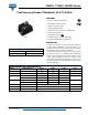
T40HFL, T70HFL, T85HFL Series
Vishay Semiconductors
Fast Recovery Diodes
(T-Modules), 40 A/70 A/85 A
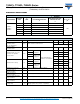
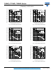
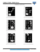
Fig. 1 - Current Ratings Characteristics
Fig. 2 - Current Ratings Characteristics
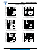
Fig. 3 - Current Ratings Characteristics
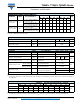
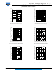
Fig. 4 - Current Ratings Characteristics
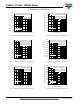
Fig. 5 - Current Ratings Characteristics
Fig. 6 - Current Ratings Characteristics
50
60
70
80
90
100
110
120
130
0 1020304050
30°
60°
90°
120°
180°
Maximum Allowable Case Temperature (°C)
Conduction Angle
Average Forward Current (A)
T4 0 HFL. . Se r i e s
R (DC) = 0.85 K/ W
thJC
50
60
70
80
90
100
110
120
130
0 10203040506070
DC
30°
60°
90°
120°
180°
Maximum Allowable Case Temperature (°C)
Conduction Period
Average Forward Current (A)
T4 0 HFL. . Se r i e s
R (DC) = 0.85 K/ W
thJC
50
60
70
80
90
100
110
120
130
0 1020304050607080
30°
60°
90°
120°
180°
Maximum Allowable Case Temperature (°C)
Conduc tion Angle
Average Forward Current (A)
T7 0 HFL. . Se r i e s
R (D C ) = 0. 5 3 K/ W
thJC
50
60
70
80
90
100
110
120
130
0 20406080100120
DC
30°
60°
90°
120°
180°
Maximum Allowable Case Temperature (°C)
Conduction Period
Average Forward Current (A)
T7 0 H FL. . Se r i e s
R (DC) = 0.53 K/ W
thJC
50
60
70
80
90
100
110
120
130
0 102030405060708090
30°
60°
90°
120°
180°
Maximum Allowable Case Temperature (°C)
Conduction Angle
Average Forwa rd Current (A)
T8 5 H FL. . Se r i e s
R (DC) = 0.46 K/ W
thJC
50
60
70
80
90
100
110
120
130
020406080100120140
DC
30°
60°
90°
120°
180°
Maximum Allowable Case Temperature (°C)
Conduction Period
Average Forward Current (A)
T8 5 H FL. . Se r i e s
R ( DC ) = 0 . 46 K/ W
thJC