6121 Baker Road, Suite 108 Minnetonka, MN 55345 Phone (952) 933-6190 Fax (952) 933-6223 1-800-274-4284 www.chtechnology.com Thank you for downloading this document from C&H Technology, Inc. Please contact the C&H Technology team for the following questions - Technical Application Assembly Availability Pricing Phone – 1-800-274-4284 E-Mail – sales@chtechnology.com www.chtechnology.com - SPECIALISTS IN POWER ELECTRONIC COMPONENTS AND ASSEMBLIES - www.chtechnology.
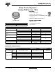
ST330CPbF Series Vishay High Power Products Phase Control Thyristors (Hockey PUK Version), 720 A FEATURES • Center amplifying gate • Metal case with ceramic insulator • International standard case TO-200AB (E-PUK) RoHS COMPLIANT • Lead (Pb)-free • Designed and qualified for industrial level TYPICAL APPLICATIONS TO-200AB (E-PUK) • DC motor controls • Controlled DC power supplies PRODUCT SUMMARY IT(AV) • AC controllers 720 A MAJOR RATINGS AND CHARACTERISTICS PARAMETER TEST CONDITIONS IT(AV) Ths
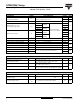
ST330CPbF Series Vishay High Power Products Phase Control Thyristors (Hockey PUK Version), 720 A ON-STATE CONDUCTION PARAMETER SYMBOL Maximum average on-state current at heatsink temperature IT(AV) Maximum RMS on-state current IT(RMS) Maximum peak, one-cycle non-repetitive surge current ITSM TEST CONDITIONS 180° conduction, half sine wave double side (single side) cooled I2√t 55 (75) °C t = 10 ms 9000 t = 8.3 ms t = 10 ms t = 8.3 ms t = 10 ms t = 8.
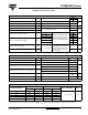
ST330CPbF Series Phase Control Thyristors Vishay High Power Products (Hockey PUK Version), 720 A TRIGGERING PARAMETER SYMBOL Maximum peak gate power PGM Maximum average gate power PG(AV) Maximum peak positive gate current IGM Maximum peak positive gate voltage + VGM Maximum peak negative gate voltage - VGM VALUES TEST CONDITIONS TYP. TJ = TJ maximum, tp ≤ 5 ms 10.0 TJ = TJ maximum, f = 50 Hz, d% = 50 2.0 TJ = TJ maximum, tp ≤ 5 ms 3.
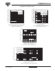
ST330CPbF Series Vishay High Power Products Phase Control Thyristors ST330C..C Series (Single Side Cooled) RthJ-hs (DC) = 0.09 K/ W 120 110 Conduction Angle 100 30° 90 60° 90° 120° 180° 80 70 0 50 100 150 200 250 300 350 400 130 ST330C..C Series (Double Side Cooled) RthJ-hs (DC) = 0.04 K/ W 120 110 100 90 80 Conduction Period 70 30° 60 60° 50 90° 120° 40 180° 30 20 DC 10 0 200 400 600 800 1000 1200 1400 1600 Average On-state Current (A) Fig.
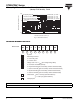
ST330CPbF Series 8000 Peak Half Sine Wave On-state Current (A) Peak Half Sine Wave On-state Current (A) Phase Control Thyristors Vishay High Power Products (Hockey PUK Version), 720 A At Any Rated Load Condition And With Rated VRRM Applied Following Surge. Initial TJ = 125°C @60 Hz 0.0083 s @50 Hz 0.0100 s 7500 7000 6500 6000 5500 5000 4500 ST330C..C Series 4000 3500 1 10 100 9000 Maximum Non Repetitive Surge Current Versus Pulse Train Duration. Control 8000 Of Conduc tion May Not Be Maintained.
ST330CPbF Series Vishay High Power Products Phase Control Thyristors (Hockey PUK Version), 720 A Rectangular gate pulse a) Recommended load line for rated di/ dt : 20V, 10ohms; tr<=1 µs b) Recommended load line for <=30% rated di/ dt : 10V, 10ohms 10 tr<=1 µs (1) PGM = 10W, (2) PGM = 20W, (3) PGM = 40W, (4) PGM = 60W, tp tp tp tp = 4 ms = 2 ms = 1 ms = 0.66 ms (a) (b) 1 Tj=-40 °C Tj=25 °C Tj=125 °C Instantaneous Gate Voltage (V) 100 (1) (2) (3) (4) VGD IGD 0.1 0.
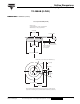
Outline Dimensions Vishay High Power Products TO-200AB (E-PUK) DIMENSIONS in millimeters (inches) Case Style TO-200AB (E-PUK) Anode to gate Creepage distance: 11.18 (0.44) minimum Strike distance: 7.62 (0.30) minimum 25.3 (0.99) DIA. MAX. 0.3 (0.01) MIN. 14.1/15.1 (0.56/0.59) 0.3 (0.01) MIN. 25.3 (0.99) DIA. MAX. Gate terminal for 1.47 (0.06) DIA. pin receptacle 40.5 (1.59) DIA. MAX. 2 holes 3.56 (0.14) x 1.83 (0.07) minimum deep 6.5 (0.26) 4.75 (0.19) 25° ± 5° 42 (1.65) MAX. 28 (1.