
Instruction Manual

www.vishay.com For technical questions, contact: ind-modules@vishay.com
Document Number: 94408
6 Revision: 06-May-08
ST330CLPbF Series
Vishay High Power Products
Phase Control Thyristors
(Hockey PUK Version), 650 A
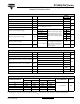
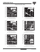
Fig. 11 - Gate Characteristics
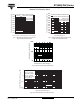
ORDERING INFORMATION TABLE
0.1
1
10
100
0.001 0.01 0.1 1 10 100
VGD
IGD
(b)
(a)
Tj = 2 5 ° C
Tj = 12 5 ° C
Tj = - 4 0 ° C
(2)
(3)
In st a n t a n e o u s G a t e C u rre n t ( A )
Instantaneous Gate Voltage (V)
a) Recommended load line for
b) Recommended load line for
<=30% rated di/dt : 10V, 10ohms
Frequenc y Limited by PG(AV)
rat ed di/ d t : 20V, 10ohms; tr<=1 µs
tr<=1 µs
(1)
(1) PGM = 10W, tp = 4ms
(2) PGM = 20W, tp = 2ms
(3) PGM = 40W, tp = 1ms
(4) PGM = 60W, tp = 0.66m s
Rectangular gate pulse
Devic e: ST330C..L Series
(4)
1 - Thyristor
2 - Essential part number
3 - 0 = Converter grade
4
- C = Ceramic PUK
5
- Voltage code x 100 = V
RRM
(see Voltage Ratings table)
6
- L = PUK case TO-200AC (B-PUK)
7
- 0 = Eyelet terminals (gate and auxiliary cathode unsoldered leads)
1 = Fast-on terminals (gate and auxiliary cathode unsoldered leads)
2 = Eyelet terminals (gate and auxiliary cathode soldered leads)
9 - Lead (Pb)-free
8 - Critical dV/dt:
None = 500 V/µs (standard selection)
L = 1000 V/µs (special selection)
3 = Fast-on terminals (gate and auxiliary cathode soldered leads)
Device code
51
324
6789
ST 33 0 C 16 L 1 - PbF
LINKS TO RELATED DOCUMENTS
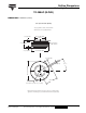
Dimensions http://www.vishay.com/doc?95076