
Instruction Manual

www.vishay.com For technical questions, contact: ind-modules@vishay.com
Document Number: 94408
4 Revision: 06-May-08
ST330CLPbF Series
Vishay High Power Products
Phase Control Thyristors
(Hockey PUK Version), 650 A
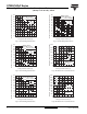
Fig. 1 - Current Ratings Characteristics
Fig. 2 - Current Ratings Characteristics
Fig. 3 - Current Ratings Characteristics
Fig. 4 - Current Ratings Characteristics
Fig. 5 - On-State Power Loss Characteristics
Fig. 6 - On-State Power Loss Characteristics
30
40
50
60
70
80
90
100
110
120
130
0 50 100 150 200 250 300 350 400 450
30°
60°
90°
120°
180°
Average On-state Current (A)
Conduction Angle
Maximum Allowable Heatsink Temperature (°C)
ST330C ..L Series
(Single Side Cooled)
R (DC) = 0.11 K/ W
thJ-hs
20
30
40
50
60
70
80
90
100
110
120
130
0200400600800
DC
30°
60°
90°
120°
180°
Average On-state Current (A)
Conduction Period
Maximum Allowable Heatsink Temperature (°C)
ST330C..L Series
(Single Side Cooled)
R (DC) = 0.11 K/ W
thJ-hs
20
30
40
50
60
70
80
90
100
110
120
130
0 200 400 600 800
30°
60°
90°
120°
180°
Average On-state Current (A)
Conduction Angle
Maximum Allowable Heatsink Temperature (°C)
ST330C..L Series
(Double Side Cooled)
R (DC) = 0.05 K/ W
thJ-hs
20
30
40
50
60
70
80
90
100
110
120
130
0 200 400 600 800 1000 1200 1400
DC
30°
60°
90°
120°
180°
Average On-state Current (A)
Conduction Period
Maximum Allowable Heatsink Temperature (°C)
ST3 3 0 C . . L Se r i e s
(Double Side Cooled)
R (DC) = 0.05 K/ W
thJ-hs
0
200
400
600
800
1000
1200
1400
1600
0 100 200 300 400 500 600 700 800
180°
120°
90°
60°
30°
RM S Li m i t
Conduc tion Angle
Maximum Average On-state Power Loss (W)
Average On-state Current (A)
ST3 3 0 C . . L Se r i e s
T = 125°C
J
0
200
400
600
800
1000
1200
1400
1600
1800
2000
2200
0200400600800100012001400
DC
180°
120°
90°
60°
30°
RM S Li m it
Conduction Period
Maximum Average On-state Power Loss (W)
Average On-state Current (A)
ST33 0 C . . L Se r i e s
T = 1 25 ° C
J