
Owner's manual

www.vishay.com For technical questions, contact: ind-modules@vishay.com
Document Number: 94406
6 Revision: 06-May-08
ST300SPbF Series
Vishay High Power Products
Phase Control Thyristors
(Stud Version), 300 A
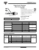
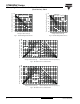
Fig. 9 - Gate Characteristics
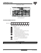
ORDERING INFORMATION TABLE
0.1
1
10
100
0.001 0.01 0.1 1 10 100
VGD
IGD
(b)
(a)
Tj = 2 5 ° C
Tj = 12 5 ° C
Tj = - 4 0 ° C
(2)
(3)
Instantaneous Gate Current (A)
Instantaneous Gate Voltage (V)
Rectangular gate pulse
a) Recommended load line for
b) Recommended load line for
<=30% rated di/dt : 10V, 10ohms
Fre q u e n c y Li m it e d b y PG ( A V )
rated di/dt : 20V, 10ohms; tr<=1 µs
tr<=1 µs
Device: ST300S Series
(1)
(1) PGM = 10W, tp = 4ms
(2) PGM = 20W, tp = 2ms
(3) PGM = 40W, tp = 1ms
(4) PGM = 60W, tp = 0.66ms
(4)
1 - Thyristor
2 - Essential part number
3 - 0 = Converter grade
4
- S = Compression bonding stud
5
- Voltage code x 100 = V
RRM
(see Voltage Ratings table)
6
- P = Stud base 3/4" 16UNF-2A threads
7
- 0 = Eyelet terminals (gate and auxiliary cathode leads)
1 = Fast-on terminals (gate and auxiliary cathode leads)
M = Stud base metric threads (M24 x 1.5)
3 = Threaded top terminal 3/8" 24UNF-2A
9 - Lead (Pb)-free
8 - Critical dV/dt:
None = 500 V/µs (standard value)
L = 1000 V/µs (special selection)
Device code
51
324
6789
ST 30 0 S 20 P 0 - PbF
LINKS TO RELATED DOCUMENTS
Dimensions http://www.vishay.com/doc?95084