
User Manual

Document Number: 94369 For technical questions, contact: ind-modules@vishay.com
www.vishay.com
Revision: 30-Apr-08 5
ST183SPbF Series
Inverter Grade Thyristors
(Stud Version), 195 A
Vishay High Power Products
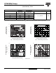
Fig. 4 - On-State Power Loss Characteristics
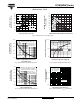
Fig. 5 - Maximum Non-Repetitive Surge Current
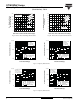
Fig. 6 - Maximum Non-Repetitive Surge Current
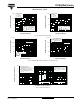
Fig. 7 - On-State Voltage Drop Characteristics
Fig. 8 - Thermal Impedance Z
thJC
Characteristics
Average On-State Current (A)
Maximum Average
On-State Power Loss (W)
0
250 300 350
50 150
100 200
0
50
100
150
200
250
300
350
400
450
500
DC
180°
120°
90°
60°
30°
RMS limit
ST183S Series
T
J
= 125 °C
Ø
Conduction period
Maximum Average On-State
Power Loss (W)
0.2 K/W
R
thSA
= 0.8 K/W - ΔR
0.3 K/W
0.4 K/W
0.5 K/W
0.8 K/W
1.2 K/W
25 50 75 100 125
Maximum Allowable Ambient Temperature (°C)
0.1 K/W
0.16 K/W
0
50
100
150
200
250
300
350
400
450
500
2000
1 10 100
2500
3000
3500
4000
4500
Number of Equal Amplitude Half Cycle
Current Pulses (N)
Peak Half Sine Wave
On-State Current (A)
Initial T
J
= 125 °C
at 60 Hz 0.0083 s
at 50 Hz 0.0100 s
ST183S Series
At any rated load condition and with
rated V
RRM
applied following surge
0.01 0.1 1
2000
2500
3000
3500
4000
5000
Pulse Train Duration (s)
Peak Half Sine Wave
On-State Current (A)
4500
Initial T
J
= 125 °C
No voltage reapplied
Rated V
RRM
reapplied
ST183S Series
Maximum non-repetitive surge current
versus pulse train duration. Control
of conduction may not be maintained
100
1.0 1.5 2.0 2.5 3.0 3.5 4.0
1000
10 000
Instantaneous On-State Current (A)
Instantaneous On-State Voltage (V)
ST183S Series
T
J
= 25 °C
T
J
= 125 °C
0.01
0.01 0.1 1 100.001
0.1
1
Square Wave Pulse Duration (s)
Z
thJC
-
Transient Thermal
Impedance (K/W)
ST183S Series
0.001
Steady state value
R
thJC
= 0.105 K/W
(DC operation)