
User Manual

www.vishay.com For technical questions, contact: ind-modules@vishay.com
Document Number: 94369
4 Revision: 30-Apr-08
ST183SPbF Series
Vishay High Power Products
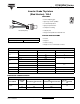
Inverter Grade Thyristors
(Stud Version), 195 A
Note
• The table above shows the increment of thermal resistance R
thJC
when devices operate at different conduction angles than DC
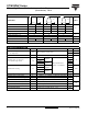
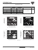
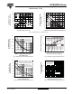
Fig. 1 - Current Ratings Characteristics Fig. 2 - Current Ratings Characteristics
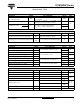
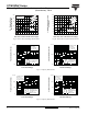
Fig. 3 - On-State Power Loss Characteristics
ΔR
thJC
CONDUCTION
CONDUCTION ANGLE
SINUSOIDAL
CONDUCTION
RECTANGULAR
CONDUCTION
TEST CONDITIONS UNITS
180° 0.016 0.012
T
J
= T
J
maximum K/W
120° 0.019 0.020
90° 0.025 0.027
60° 0.036 0.037
30° 0.060 0.060
0
Maximum Allowable
Case Temperature (°C)
Average On-State Current (A)
40 80 120 160
80
90
100
110
120
130
20 60 100 140 180 200
ST183S Series
R
thJC
(DC) = 0.105 K/W
Ø
Conduction angle
30 °C
60 °C
90 °C
180 °C
120 °C
0
250 300 350
Average On-State Current (A)
50 150
100 200
Maximum Allowable
Case Temperature (°C)
70
80
90
100
110
120
130
ST183S Series
R
thJC
(DC) = 0.105 K/W
Ø
Conduction period
30°
60°
90°
120°
180°
DC
Average On-State Current (A)
Maximum Average On-State
Power Loss (W)
0
50
100
150
200
250
300
350
0
100 120 140 160 180 200
20 6040 80
RMS limit
180°
120°
90°
60°
30°
Ø
Conduction angle
ST183S Series
T
J
= 125 °C
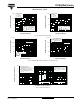
Maximum Allowable Ambient Temperature (°C)
Maximum Average On-State
Power Loss (W)
0
50
100
150
200
250
300
350
25
125
50 10075
R
thSA
= 0.08 K/W - ΔR
0.1 K/W
0.16 K/W
0.2 K/W
0.3 K/W
0.4 K/W
0.8 K/W
1.2 K/W
0.5 K/W