
Instruction Manual

www.vishay.com For technical questions, contact: ind-modules@vishay.com
Document Number: 94397
6 Revision: 30-Apr-08
ST180SPbF Series
Vishay High Power Products
Phase Control Thyristors
(Stud Version), 200 A
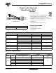
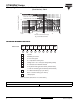
Fig. 9 - Gate Characteristics
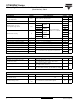
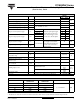
ORDERING INFORMATION TABLE
0.1
1
10
100
0.001 0.01 0.1 1 10 100
VGD
IGD
(b)
(a)
Tj = 2 5 ° C
Tj = 1 2 5 ° C
Tj = - 4 0 ° C
(1) (2)
(3)
In st a n t a n e o u s G a t e C u r r e n t ( A )
Instantaneous Gate Voltage (V)
Rectangular gate pulse
a) Recommended load line for
b) Recommended load line for
<=30% rated di/ dt : 10V, 10ohms
Frequency Limited by PG(AV)
rated di/dt : 20V, 10ohms; tr<=1 µs
tr<=1 µs
(1) PGM = 10W, tp = 4ms
(2) PGM = 20W, tp = 2ms
(3) PGM = 40W, tp = 1ms
(4) PGM = 60W, tp = 0.66ms
D e v i c e : ST18 0 S Se r i e s
(4)
1
- Thyristor
2
- Essential part number
3
- 0 = Converter grade
4
9
- Lead (Pb)-free
- S = Compression bonding stud
8
- V = Glass-metal seal (only up to 1200 V)
5
- Voltage code x 100 = V
RRM
(see Voltage Ratings table)
6
- P = Stud base 3/4"-16UNF2A threads
7
- 0 = Eyelet terminals (gate and auxiliary cathode leads)
1 = Fast-on terminals (gate and auxiliary cathode leads)
None = Ceramic housing (over 1200 V)
Note: For metric device M16 x 1.5 contact factory
Device code
51
324
6789
ST 18 0 S 20 P 0 PbF-
LINKS TO RELATED DOCUMENTS
Dimensions http://www.vishay.com/doc?95082