
Instruction Manual

Document Number: 94397 For technical questions, contact: ind-modules@vishay.com
www.vishay.com
Revision: 30-Apr-08 5
ST180SPbF Series
Phase Control Thyristors
(Stud Version), 200 A
Vishay High Power Products
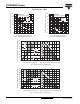
Fig. 5 - Maximum Non-Repetitive Surge Current
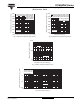
Fig. 6 - Maximum Non-Repetitive Surge Current
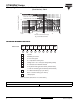
Fig. 7 - On-State Voltage Drop Characteristics
Fig. 8 - Thermal Impedance Z
thJC
Characteristics
2000
2400
2800
3200
3600
4000
4400
4800
110100
Number Of Equal Amplitude Half Cycle Current Pulses (N)
Pea k Ha lf Sine Wave On-state Current (A)
Initia l T = 125°C
@ 60 Hz 0.0083 s
@ 50 Hz 0.0100 s
J
ST1 8 0 S Se r i e s
At Any Rated Load Condition And With
Rated V Ap plied Following Surge.
RRM
2000
2500
3000
3500
4000
4500
5000
5500
0.01 0.1 1
Pulse Tra in Du ra t ion ( s)
Versus Pulse Train Duration. Control
Peak Half Sine Wave On-state Current (A)
Initial T = 125°C
No Volta g e Reapplied
Ra t e d V Re a p p l i e d
RRM
J
ST180S Series
Maximum Non Repetitive Surge Current
Of Conduction May Not Be Maintained.
100
1000
10000
0.5 1 1.5 2 2.5 3 3.5 4 4.5 5 5.5 6
T = 2 5 ° C
J
Instantaneous On-state Current (A)
Instantaneous On-state Voltage (V)
T = 125°C
J
ST1 8 0 S Se r i e s
0.001
0.01
0.1
1
0.001 0.01 0.1 1 10
Square Wave Pulse Duration (s)
thJC
Transient Thermal Impedance Z (K/W)
ST1 8 0 S Se r i e s
Steady State Value
R = 0.105 K/ W
(DC Operation)
thJC