
Instruction Manual

www.vishay.com For technical questions, contact: ind-modules@vishay.com
Document Number: 94397
4 Revision: 30-Apr-08
ST180SPbF Series
Vishay High Power Products
Phase Control Thyristors
(Stud Version), 200 A
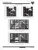
Fig. 1 - Current Ratings Characteristics Fig. 2 - Current Ratings Characteristics
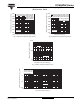
Fig. 3 - On-State Power Loss Characteristics
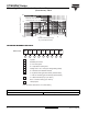
Fig. 4 - On-State Power Loss Characteristics
80
90
100
110
120
130
0 40 80 120 160 200 240
Maximum Allowable Case Temperature (°C)
30°
60°
90°
120°
180°
Average On-state Current (A)
Conduction Angle
ST1 8 0 S Se r i e s
R (DC) = 0.105 K/ W
thJC
70
80
90
100
110
120
130
0 50 100 150 200 250 300 350
DC
30°
60°
90°
120°
180°
Average On-st a te Curre nt (A)
Maximum Allowable Case Temperature (°C)
Conduction Period
ST1 8 0S Se r i e s
R (DC) = 0.105 K/ W
thJC
25 50 75 100 125
Maximum Allowable Ambient Temperature (°C)
R
=
0
.
0
8
K
/
W
-
D
e
l
t
a
R
t
h
S
A
0.
1
K/
W
0
.
1
6
K
/
W
0
.
2
K
/
W
0
.
3
K
/
W
0
.
4
K
/
W
0
.
5
K
/
W
0
.
8
K
/
W
1
.
2
K
/
W
0
50
100
150
200
250
300
350
0 40 80 120 160 200 240
180°
120°
90°
60°
30°
RM S Lim it
Conduction Angle
Maximum Average On-state Power Loss (W)
Average On-state Current (A)
ST1 8 0 S Se r i e s
T = 1 2 5° C
J
25 50 75 100 125
Maximum Allowable Ambient Temperature (°C)
R
=
0
.
0
8
K
/
W
-
D
e
l
t
a
R
t
h
S
A
0
.
1
K
/
W
0
.
1
6
K
/
W
0
.
2
K
/
W
0
.
3
K
/
W
0
.
4
K
/
W
0
.
5
K
/
W
0
.
8
K/
W
1
.
2
K
/
W
0
50
100
150
200
250
300
350
400
450
500
0 40 80 120 160 200 240 280 320
DC
180°
120°
90°
60°
30°
RM S Lim it
Conduction Period
Maximum Average On-state Power Loss (W)
Average On-state Current (A)
ST180S Se rie s
T = 12 5 ° C
J