6121 Baker Road, Suite 108 Minnetonka, MN 55345 Phone (952) 933-6190 Fax (952) 933-6223 1-800-274-4284 www.chtechnology.com Thank you for downloading this document from C&H Technology, Inc. Please contact the C&H Technology team for the following questions - Technical Application Assembly Availability Pricing Phone – 1-800-274-4284 E-Mail – sales@chtechnology.com www.chtechnology.com - SPECIALISTS IN POWER ELECTRONIC COMPONENTS AND ASSEMBLIES - www.chtechnology.
ST180SPbF Series Vishay High Power Products Phase Control Thyristors (Stud Version), 200 A FEATURES • Center amplifying gate • International standard case TO-209AB (TO-93) RoHS • Hermetic metal case with ceramic insulator COMPLIANT (Also available with glass-metal seal up to 1200 V) • Compression bonded encapsulation for heavy duty operations such as severe thermal cycling • Lead (Pb)-free TO-209AB (TO-93) • Designed and qualified for industrial level TYPICAL APPLICATIONS PRODUCT SUMMARY • DC motor
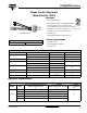
ST180SPbF Series Vishay High Power Products Phase Control Thyristors (Stud Version), 200 A ON-STATE CONDUCTION PARAMETER SYMBOL Maximum average on-state current at case temperature IT(AV) Maximum RMS on-state current IT(RMS) Maximum peak, one-cycle non-repetitive surge current ITSM TEST CONDITIONS 180° conduction, half sine wave I2√t 85 °C t = 10 ms 5000 t = 8.3 ms t = 10 ms t = 8.3 ms t = 10 ms t = 8.
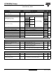
ST180SPbF Series Phase Control Thyristors (Stud Version), 200 A Vishay High Power Products TRIGGERING PARAMETER Maximum peak gate power Maximum average gate power SYMBOL PGM PG(AV) Maximum peak positive gate current IGM Maximum peak positive gate voltage + VGM Maximum peak negative gate voltage - VGM VALUES TEST CONDITIONS TYP. TJ = TJ maximum, tp ≤ 5 ms 10 TJ = TJ maximum, f = 50 Hz, d% = 50 2.0 TJ = TJ maximum, tp ≤ 5 ms 3.
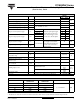
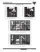
ST180SPbF Series Vishay High Power Products Phase Control Thyristors Maximum Allowable Case Temperature (°C) 130 ST180S Series RthJC (DC) = 0.105 K/ W 120 110 Conduc tion Angle 30° 100 60° 90° 120° 90 180° 80 0 40 80 120 160 200 240 130 ST180S Series R thJC (DC) = 0.105 K/ W 120 110 Conduc tion Period 100 90 30° 80 60° 90° 120° 180° DC 70 0 50 100 150 200 250 300 350 Average On-state Current (A) Average On-state Current (A) Fig. 1 - Current Ratings Characteristics Fig.
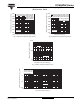
ST180SPbF Series 4800 Peak Half Sine Wave On-state Current (A) Peak Half Sine Wave On-state Current (A) Phase Control Thyristors (Stud Version), 200 A At Any Rated Load Condition And With Rated VRRM Applied Following Surge. 4400 Initial TJ = 125°C @ 60 Hz 0.0083 s @ 50 Hz 0.0100 s 4000 3600 3200 2800 2400 ST180SSeries 2000 1 10 100 Vishay High Power Products 5500 Maximum Non Repetitive Surge Current Versus Pulse Train Duration. Control 5000 Of Conduction May Not Be Maintained.
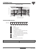
ST180SPbF Series Vishay High Power Products Phase Control Thyristors (Stud Version), 200 A Rec tangular gate pulse a) Recommended load line for rated di/ dt : 20V, 10ohms; tr<=1 µs b) Rec ommended load line for <=30% rated di/ dt : 10V, 10ohms 10 tr<=1 µs (b) VGD IGD 0.1 0.001 (1) PGM = 10W, (2) PGM = 20W, (3) PGM = 40W, (4) PGM = 60W, = 4ms = 2ms = 1ms = 0.66ms (a) (1) Device: ST180S Series 0.