
Owner's manual

www.vishay.com For technical questions, contact: ind-modules@vishay.com
Document Number: 94396
6 Revision: 30-Apr-08
ST180CPbF Series
Vishay High Power Products
Phase Control Thyristors
(Hockey PUK Version), 350 A
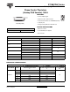
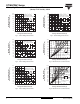
Fig. 11 - Gate Characteristics
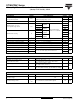
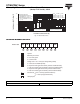
ORDERING INFORMATION TABLE
0.1
1
10
100
0.001
Instantaneous Gate Current (A)
Instantaneous Gate Voltage (V)
0.01 0.1 1 10 100
T
J
= 25 °C
T
J
= 40 °C
T
J
= 125 °C
(b)
(1) (2)
(3) (4)
(1) P
GM
= 10 W, t
p
= 4 ms
(2) P
GM
= 20 W, t
p
= 2 ms
(3) P
GM
= 40 W, t
p
= 1 ms
(4) P
GM
= 60 W, t
p
= 0.66 ms
Frequency limited by P
G(AV)
V
GD
I
GD
Rectangular gate pulse
a) Recommended load line for
rated dI/dt: 20 V, 10 Ω; t
r
≤ 1 µs
b) Recommended load line for
≤ 30 % rated dI/dt: 10 V, 10 Ω
t
r
≤ 1 µs
Device: ST180C..C Series
(a)
1
- Thyristor
2
- Essential part number
3
- 0 = Converter grade
4
9
- Lead (Pb)-free
- C = Ceramic PUK
8
- Critical dV/dt:
5
- Voltage code x 100 = V
RRM
(see Voltage Ratings table)
6
- C = PUK case TO-200AB (A-PUK)
7
- 0 = Eyelet terminals (gate and auxiliary cathode unsoldered leads)
1 = Fast-on terminals (gate and auxiliary cathode unsoldered leads)
2 = Eyelet terminals (gate and auxiliary cathode soldered leads)
3 = Fast-on terminals (gate and auxiliary cathode soldered leads)
None = 500 V/µs (standard selection)
L = 1000 V/µs (special selection)
Device code
51
324
6789
ST 18 0 C 20 C 1 - PbF
LINKS TO RELATED DOCUMENTS
Dimensions http://www.vishay.com/doc?95074