
Instruction Manual

www.vishay.com For technical questions, contact: ind-modules@vishay.com
Document Number: 94366
4 Revision: 29-Apr-08
ST173CPBF Series
Vishay High Power Products
Inverter Grade Thyristors
(Hockey PUK Version), 330 A
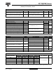
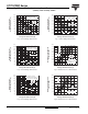
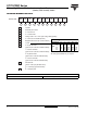
Fig. 1 - Current Ratings Characteristics
Fig. 2 - Current Ratings Characteristics
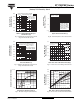
Fig. 3 - Current Ratings Characteristics
Fig. 4 - Current Ratings Characteristics
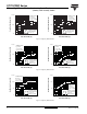
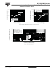
Fig. 5 - On-State Power Loss Characteristics
Fig. 6 - On-State Power Loss Characteristics
0
200
Maximum Allowable
Heatsink Temperature (°C)
Average On-State Current (A)
40
80
240120 160
40
50
60
70
80
90
100
110
120
130
ST173C..C Series
(Single side cooled)
R
thJ-hs
(DC) = 0.17 K/W
Ø
Conduction angle
60°
30°
90°
120°
180°
0
250 300 350
Average On-state Current (A)
50 150
100 200
Maximum Allowable
Heatsink Temperature (°C)
20
30
40
50
60
70
80
90
100
110
120
130
ST173C..C Series
(Single side cooled)
R
thJ-hs
(DC) = 0.17 K/W
Ø
Conduction period
30° 60°
90°
120°
180°
DC
0
250 300 350 400
Average On-State Current (A)
50 150
100 200
Maximum Allowable
Heatsink Temperature (°C)
30
40
50
60
70
80
90
100
110
120
130
30°
60°
90°
120°
180°
ST173C..C Series
(Double side cooled)
R
thJ-hs
(DC) = 0.08 K/W
Ø
Conduction angle
Average On-State Current (A)
Maximum Allowable
Heatsink Temperature (°C)
0
500 600 700
100 300
200 400
20
30
40
50
60
70
80
90
100
110
120
130
ST173C..C Series
(Double side cooled)
R
thJ-hs
(DC) = 0.08 K/W
Ø
Conduction period
DC
30°
60°
90°
120°
180°
Average On-State Current (A)
Maximum Average On-State
Power Loss (W)
0
100
200
300
400
500
600
700
800
900
1000
RMS limit
0
250 300 350 400 450
50 150
100 200
180°
120°
90°
60°
30°
Ø
Conduction angle
ST173C..C Series
T
J
= 125 °C
Average On-State Current (A)
Maximum Average On-State
Power Loss (W)
0
200
400
600
800
1000
1200
1400
0
300 400 500 600 700
100 200
DC
180°
120°
90°
60°
30°
RMS limit
ST173C..C Series
T
J
= 125 °C
Ø
Conduction period