6121 Baker Road, Suite 108 Minnetonka, MN 55345 Phone (952) 933-6190 Fax (952) 933-6223 1-800-274-4284 www.chtechnology.com Thank you for downloading this document from C&H Technology, Inc. Please contact the C&H Technology team for the following questions - Technical Application Assembly Availability Pricing Phone – 1-800-274-4284 E-Mail – sales@chtechnology.com www.chtechnology.com - SPECIALISTS IN POWER ELECTRONIC COMPONENTS AND ASSEMBLIES - www.chtechnology.
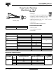
ST110SPbF Series Vishay High Power Products Phase Control Thyristors (Stud Version), 110 A FEATURES • Center gate • International standard case TO-209AC (TO-94) • Compression bonded encapsulation for heavy duty operations such as severe thermal cycling • Hermetic glass-metal case with (Glass-metal seal over 1200 V) TO-209AC (TO-94) ceramic RoHS COMPLIANT insulator • Lead (Pb)-free • Designed and qualified for industrial level TYPICAL APPLICATIONS PRODUCT SUMMARY IT(AV) • DC motor controls 110 A •
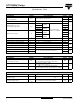
ST110SPbF Series Vishay High Power Products Phase Control Thyristors (Stud Version), 110 A ON-STATE CONDUCTION PARAMETER SYMBOL Maximum average on-state current at case temperature IT(AV) Maximum RMS on-state current IT(RMS) Maximum peak, one-cycle non-repetitive surge current ITSM TEST CONDITIONS 180° conduction, half sine wave I2√t 90 °C t = 10 ms 2700 t = 8.3 ms t = 10 ms t = 8.3 ms t = 10 ms t = 8.
ST110SPbF Series Phase Control Thyristors (Stud Version), 110 A Vishay High Power Products TRIGGERING PARAMETER SYMBOL Maximum peak gate power PGM Maximum average gate power PG(AV) Maximum peak positive gate current IGM Maximum peak positive gate voltage + VGM Maximum peak negative gate voltage - VGM VALUES TEST CONDITIONS TYP.
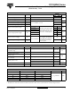
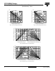
ST110SPbF Series Vishay High Power Products Phase Control Thyristors (Stud Version), 110 A 130 ST110S Series RthJC (DC) = 0.195 K/W Maximum Allowable Case Temperature (°C) Maximum Allowable Case Temperature (°C) 130 120 110 Conduction Angle 100 90 30° 60° 90° 120° 180° 80 0 20 40 60 80 100 120 ST110S Series RthJC (DC) = 1.95 K/W 120 110 Conduction Period 30° 100 60° 90 90° 120° 180° 80 0 20 Average On-state Current (A) A S R th W K/ .
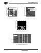
ST110SPbF Series Phase Control Thyristors (Stud Version), 110 A At Any Rated Load Condition And With Rated VRRM Applied Following Surge. Initial TJ = 125°C @ 60 Hz 0.0083 s @ 50 Hz 0.0100 s 2200 2000 1800 1600 1400 1200 ST110S Series 1000 1 10 2800 Maximum Non Repetitive Surge Current Versus Pulse Train Duration. Control Of Conduction May Not Be Maintained.
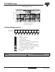
ST110SPbF Series Vishay High Power Products Phase Control Thyristors (Stud Version), 110 A 100 Instantaneous Gate Voltage (V) Rectangular gate pulse a) Recommended load line for rated di/dt : 20V, 10ohms; tr<=1 µs b) Recommended load line for <=30% rated di/dt : 10V, 10ohms 10 tr<=1 µs (1) PGM = 10W, (2) PGM = 20W, (3) PGM = 40W, (4) PGM = 60W, tp = 4ms tp = 2ms tp = 1ms tp = 0.66ms (a) (b) IGD 0.1 0.