
User Manual

www.vishay.com For technical questions, contact: ind-modules@vishay.com
Document Number: 94334
4 Revision: 29-Apr-08
ST083SPbF Series
Vishay High Power Products
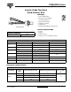
Inverter Grade Thyristors
(Stud Version), 85 A
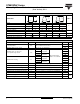
Note
• The table above shows the increment of thermal resistance R
thJC
when devices operate at different conduction angles than DC
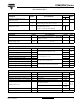
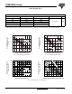
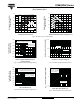
Fig. 1 - Current Ratings Characteristics Fig. 2 - Current Ratings Characteristics
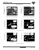
Fig. 3 - On-State Power Loss Characteristics
ΔR
thJC
CONDUCTION
CONDUCTION ANGLE SINUSOIDAL CONDUCTION RECTANGULAR CONDUCTION TEST CONDITIONS UNITS
180° 0.034 0.025
T
J
= T
J
maximum K/W
120° 0.041 0.042
90° 0.052 0.056
60° 0.076 0.079
30° 0.126 0.127
ST083S Series
R
thJC
(DC) = 0.195 K/W
110
100
90
80
130
030
60
90
Maximum Allowable Case
Temperature (°C)
Average On-State Current (A)
10 40 7020 50 80
120
30° 60° 90° 120° 180°
Ø
Conduction angle
ST083S Series
R
thJC
(DC) = 0.195 K/W
110
100
90
70
130
060
120
140
Maximum Allowable Case
Temperature (°C)
Average On-State Current (A)
20 8040 100
120
30°
60°
90°
120°
180°
80
DC
Ø
Conduction period
0
20
40
60
80
100
120
140
160
180
0 102030405060708090
180°
120°
90°
60°
30°
RMS limit
Conduction angle
Maximum Average On-State
Power Loss (W)
Average On-State Current (A)
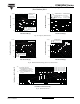
ST083S Series
T
J
= 125 °C
Ø
Maximum Allowable Ambient Temperature (°C)
0
20
25 50 75 100 125
40
60
80
100
120
140
160
180
Maximum Average On-State
Power Loss (W)
0.2 K/W
R
thSA
= 0.1 K/W - ΔR
0.3 K/W
0.4 K/W
0.5 K/W
0.8 K/W
1.2 K/W