
Manual


Document Number: 50035 For technical questions, contact: sfer@vishay.com
www.vishay.com
Revision: 24-Nov-08 3
RTO 50
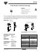
Power Resistor, Thick Film Technology
Vishay Sfernice
OVERLOADS
The applied voltage must always be lower than the maximum
overload voltage of 450 V.
The values indicated on the graph below are applicable to
resistors in air or mounted onto a heatsink.
MARKING
Model, Style, Resistance Value (in Ω), Tolerance (in %),
Manufacturing Date, VISHAY trademark.
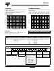
POWER RATING CHART
The temperature of the heatsink should be maintained within
the limits specified.
To improve the thermal conductivity, surfaces in contact
should be coated with a silicone grease and the torque
applied on the screw for tightening should be around 1 Nm.
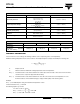
ENERGY IN JOULES
0.01
0.1
1
10
10
10
10
10
10
-6
-5
-4
-3 -2
ENERGY CURVE
OVERLOAD DURATION IN S
PACKAGING
Tube of 50 units
HEATSINK TEMPERATURE IN °C
% RATED POWER
100
75
50
25
0
0 25 40 60 80 100 120 140 155
ORDERING INFORMATION
RTO 50 F 100K ± 1% XXX TU50 e1
MODEL STYLE CONNECTIONS
F: Radial leads
C: Surface mount
RESISTANCE VALUE TOLERANCE
± 1%
± 2%
± 5%
± 10%
CUSTOM DESIGN
Optional
on request:
special TCR,
shap, etc.
PACKAGING LEAD (Pb)-free
GLOBAL PART NUMBER INFORMATION
GLOBAL
MODEL
SIZE LEADS OHMIC VALUE TOLERANCE PACKAGING
RTO 050 F = Radial leads
C = Surface mount
The firts four digits are
significant figures and the last
digit specifies the number of
zeros to follow.
R designates decimal point.
48R70 = 48.7 Ω
48701 = 48 700 Ω
10002 = 100 000 Ω
R0100 = 0.01 Ω
R6800 = 0.68 Ω
27000 = 2700 Ω = 2K7 Ω
F = 1 %
G = 2 %
J = 5 %
K = 10 %
T = Tube
Size 30 and 50:
Tube 50 pieces
050FR68 0T1T OR 0JE