
Owner's manual

PS22052
Intellimod™ Module
Dual-In-Line Intelligent Power Module
5 Amperes/1200 Volts
Powerex, Inc., 200 E. Hillis Street, Youngwood, Pennsylvania 15697-1800 (724) 925-7272
6 Rev. 10/05
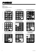
Protection Function Timing Diagrams
A1
A4
A5
A2
SC
A7
A3
SET RESET
RC FILTER TIME
CONSISTANT DELAY
SC REFERENCE VOLTAGE
A6
A8
LOWER-SIDE
CONTROL INPUT
PROTECTION
CIRCUIT STATE
INTERNAL IGBT GATE
OUTPUT CURRENT I
C
SENSE VOLTAGE ON
THE SHUNT RESISTOR
FA
ULT OUTPUT F
O
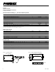
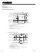
Short-Circuit Protection (N-side only, with external shunt resistor and CR filter)
A1: Normal operation – IGBT turn on and conducting current.
A2: Short-circuit current detected (SC trigger).
A3: IGBT gate hard interrupted.
A4: IGBT turn off.
A5: F
O
output with a fixed pulse width (determined by the external capacitance C
FO
).
A6: Input “L” – IGBT off.
A7: Input “H” – IGBT on is blocked during the F
O
output period.
A8: IGBT stays in off state.
B1
B4
B5
B2
UV
Dt
B7
B3
SET RESETRESET
UV
Dr
B6
CONTROL INPUT
PROTECTION
CIRCUIT STATE
CONTROL SUPPLY
VOLTA
GE V
D
OUTPUT CURRENT I
C
FA
ULT OUTPUT F
O
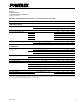
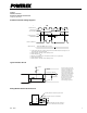
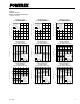
Under-Voltage Protection (N-side, UV
D
)
B1: Control supply voltage rise – After the voltage level reaches UV
Dr
, the drive circuit begins to work
at the rising edge of the next input signal.
B2 : Normal operation – IGBT turn on and conducting current.
B3: Under-voltage trip (UV
Dt
).
B4: IGBT turn off regardless of the control input level.
B5: F
O
asserted during the period from minimum pulse width or until control supply recover to UV
Dr
.
B6: Under-voltage reset (UV
Dr
).
B7: Normal operation – IGBT turn on and conducting current.