
Owner's manual
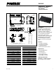

PS22052
Intellimod™ Module
Dual-In-Line Intelligent Power Module
5 Amperes/1200 Volts
Powerex, Inc., 200 E. Hillis Street, Youngwood, Pennsylvania 15697-1800 (724) 925-7272
4 Rev. 10/05
Thermal Characteristics
Characteristic Symbol Condition Min. Typ. Max. Units
Junction to Case R
th(j-c)Q
IGBT Part (Per 1/6 Module) — — 2.61 °C/Watt
Thermal Resistance R
th(j-c)D
FWDi Part (Per 1/6 Module) — — 3.81 °C/Watt
Contact Thermal resistance R
th(c-f)
Per 1 Module — — 0.047 °C/Watt
Recommended Conditions for Use
Characteristic Symbol Condition Min. Typ. Value Units
Supply Voltage V
CC
Applied between P-NU, NV, NW 350 600 800 Volts
Control Supply Voltage V
D
Applied between V
P1
-V
PC
, V
N1
-V
NC
13.5 15.0 16.5 Volts
V
DB
Applied between
13.5 15.0 16.5 Volts
V
UFB
-V
UFS
, V
VFB
-V
VFS
, V
WFB
-V
WFS
Control Supply Variation
dV
D
, dV
DB
— -1 — 1 V/µs
Arm Shoot-through Blocking Time t
DEAD
For Each Input Signal, T
C
≤ 100°C 3.3 — — µs
PWM Input Frequency f
PWM
T
j
≤ 125°C, T
C
≤ 100°C — — 15 kHz
Output r.m.s. Current* I
O
V
CC
= 600V, V
D
= V
DB
= 15V,
f
C
= 5kHz — — 5.5 A
rms
P.F. = 0.8, Sinusoidal PWM, T
j
≤ 125°C, T
f
≤ 100°C
V
CC
= 600V, V
D
= V
DB
= 15V,
f
C
= 15kHz — — 3.2 A
rms
P.F. = 0.8, Sinusoidal PWM, T
j
≤ 125°C, T
f
≤ 100°C
Allowable Minimum Input P
WIN(on)
** — 1.5 — —
µs
Pulse Width P
WIN(off)***
I
C
≤ 5A 350 ≤ V
CC
≤ 800V, 13.5 ≤ V
D
≤ 16.5V, 2.6 — — µs
5 < I
C
≤ 8.5A 13.5 ≤ V
DB
≤ 16.5V, -20 ≤ T
C
≤ 100°C 2.8 — — µs
N Line Wiring Inductance Less than 10nH
V
NC
Voltage Variation V
NC
Between V
NC
-NU, NV, NW (Including Surge) -5.0 — 5.0 Volts
*The allowable r.m.s. current also depends on the user application conditions.
**DIP-IPM might make no response to the input ON signal with pulse width less than P
WIN(on)
.
***DIP-IPM might make no response or not work properly if the input OFF signal pulse width is less than P
WIN(off)
.