
User Manual

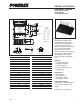

PS21997-4, PS21997-4A
Intellimod™ Module
Dual In-line Intelligent Power Module
30 Amperes/600 Volts
Powerex, Inc., 173 Pavilion Lane, Youngwood, Pennsylvania 15697-1800 (724) 925-7272
6 10/09
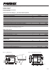
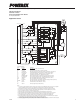
Protection Function Timing Diagrams
a1
SC
SC REFERENCE VOLTAGE
RC CIRCUIT TIME CONSTANT DELAY
a2
a3
a4
a8
a5
a7a6
SET
RESET
N-SIDE
CONTROL INPUT
PROTECTION
CIRCUIT STATE
INTERNAL IGBT GATE
SENSE VOLTAGE OF R
S
OUTPUT CURRENT I
C
FAULT OUTPUT F
O
Short Circuit Protection (N-side Only with External Shunt Resistor and RC Filter)
a1: Normal operation – IGBT turns on and carries current.
a2: Short circuit current is detected (SC trigger).
a3: All N-side IGBT's gate are hard interrupted.
a4: All N-side IGBT's turn off.
a5: F
O
output wirh a fixed pulse width (determined by the external capacitance C
FO
).
a6: Input "L" – IGBT off.
a7: Input "H" – IGBT on, but during the F
O
output perid the IGBT will not turn on.
a8: IGBT turns on when L→H signal is input after F
O
is reset.
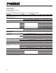
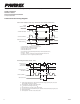
b1
b4
b5
b2
UV
Dt
b7
b3
SET
RESETRESET
UV
Dr
b6
CONTROL INPUT
PROTECTION
CIRCUIT STATE
CONTROL SUPPLY
VOLTAGE V
D
OUTPUT CURRENT I
C
FAULT OUTPUT F
O
Under-Voltage Protection (N-side , UV
D
)
b1: Control supply voltage V
D
rises – After V
D
level reaches under voltage reset level (UV
Dr
), the circuits
start to operate when next input is applied.
b2 : Normal operation – IGBT turns on and carries current.
b3: V
D
level dips to under voltage trip level (UV
Dt
).
b4: All N-side IGBT’s turn off in spite of control input condition.
b5: F
O
is low for a minimum period determined by the capacitance C
FO
but continuously during UV period.
b6: V
D
level reaches UV
Dr
.
b7: Normal operation – IGBT turns on and carries current.