
Manual
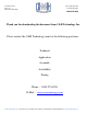


PS21962-4, PS21962-4A, PS21962-4C
Intellimod™ Module
Dual-In-Line Intelligent Power Module
5 Amperes/600 Volts
Powerex, Inc., 173 Pavilion Lane, Youngwood, Pennsylvania 15697-1800 (724) 925-7272
2 Rev. 12/09
Absolute Maximum Ratings, T
j
= 25°C unless otherwise specied
PS21962-4, PS21962-4A
Characteristics Symbol PS21962-4C Units
Power Device Junction Temperature* T
j
-20 to 150 °C
Storage Temperature T
stg
-40 to 125 °C
Case Operating Temperature (Note 1) T
C
-20 to 100 °C
Mounting Torque, M3 Mounting Screws — 6 in-lb
Module Weight (Typical) — 10 Grams
Heatsink Flatness (Note 2) — -50 to 100 µm
Self-protection Supply Voltage Limit (Short Circuit Protection Capability)** V
CC(prot.)
400 Volts
Isolation Voltage, AC 1 minute, 60Hz Sinusoidal, Connection Pins to Heatsink Plate V
ISO
1500 Volts
*The ma ximum junction temperature rating of the power chips integrated within the DIP-IPM is 150°C (@T
C
≤ 100°C). However, to ensure safe operation of the DIP-IPM,
the average junction temperature should be limited to T
j(avg)
≤125°C (@T
C
≤ 100°C).
**V
D
= 13.5 ~ 16.5V, Inverter Part, T
j
= 125°C, Non-repetitive, Less than 2µs
IGBT Inverter Sector
Collector-Emitter Voltage V
CES
600 Volts
Each Collector Current, ± (T
C
= 25°C) I
C
5 Amperes
Each Peak Collector Current, ± (T
C
= 25°C, Less than 1ms) I
CP
10 Amperes
Supply Voltage (Applied between P - N) V
CC
450 Volts
Supply Voltage, Surge (Applied between P - N) V
CC(surge)
500 Volts
Collector Dissipation (T
C
= 25°C, per 1 Chip) P
C
21.3 Watts
Control Sector
Supply Voltage (Applied between V
P1
-V
NC
, V
N1
-V
NC
) V
D
20 Volts
Supply Voltage (Applied between V
UFB
-U,
V
VFB
-V, V
WFB
-W) V
DB
20 Volts
Input Voltage (Applied between U
P
, V
P
, W
P
-V
NC
, U
N
, V
N
, W
N
-V
NC
) V
IN
-0.5 ~ V
D
+0.5 Volts
Fault Output Supply Voltage (Applied between F
O
-V
NC
) V
FO
-0.5 ~ V
D
+0.5 Volts
Fault Output Current (Sink Current at F
O
Terminal) I
FO
1 mA
Current Sensing Input Voltage (Applied between C
IN
-V
NC
) V
SC
-0.5 ~ V
D
+0.5 Volts
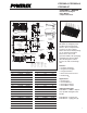
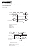
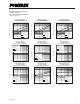
Note 1 – T
C
Measure Point
FWDi
CHIP
POWER TERMINALS
CONTROL TERMINALS
IGBT
CHIP
HEATSINK SIDE
T
C
POINT
11.6mm
3.0mm
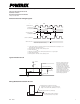
DIP-IPM
HEATSINK
MEASUREMENT POINT
4.6mm
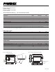
PLACE TO CONTACT
A HEATSINK
HEATSINK
–
+
–+
Note 2 – Flatness Measurement Position