
User Manual

PS21765
Intellimod™ Module
Dual-In-Line Intelligent Power Module
20 Amperes/600 Volts
Powerex, Inc., 173 Pavilion Lane, Youngwood, Pennsylvania 15697 (724) 925-7272
5Rev. 07/07
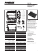
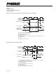
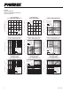
Short Circuit Protection (Lower-arms Only with External Shunt Resistor and RC Filter)
A1
SC
SC REFERENCE VOLTAGE
CR CIRCUIT TIME CONSTANT DELAY
A2
A3
A4
A8
A5
A7A6
SET
RESET
LOWER-ARMS
CONTROL INPUT
PROTECTION
CIRCUIT STATE
INTERNAL IGBT GATE
SENSE VOLTAGE OF
THE SHUNT RESISTOR
OUTPUT CURRENT I
C
FAULT OUTPUT F
O
A. Short Circuit Protection (Lower-arms Only with External Shunt Resistor and RC Filter)
A1: Normal operation – IGBT ON and carrying current.
A2: Short Circuit current detection (SC trigger).
A3: IGBT gate hard interruption.
A4: IGBT turns OFF.
A5: F
O
timer operation starts. The pulse width of the F
O
signal is set by the external capacitor C
FO
.
A6: Input "L" – IGBT OFF.
A7: Input "H"
A8: IGBT OFF state in spite of input "H".
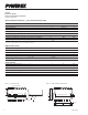
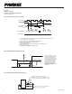
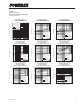
B1
B4
B5
B2
UV
Dt
B7
B3
SET
RESETRESET
UV
Dr
B6
CONTROL INPUT
PROTECTION
CIRCUIT STATE
CONTROL SUPPLY
VOLTAGE V
D
OUTPUT CURRENT I
C
FAULT OUTPUT F
O
B. Under-Voltage Protection (Lower-arm, UV
D
)
B1: Control supply voltage risinge – After the voltage level reaches UV
Dr
, the drive circuit begins to
work at the rising edge of the next input signal.
B2 : Normal operation – IGBT ON and conducting current.
B3: Under-voltage trip (UV
Dt
).
B4: IGBT turns OFF regardless of the control input level.
B5: F
O
operation starts.
B6: Under-voltage reset (UV
Dr
).
B7: Normal operation – IGBT ON and conducting current.
Under-Voltage Protection (Lower-arm, UV
D
)