
User Manual
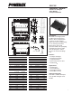

PS21765
Intellimod™ Module
Dual-In-Line Intelligent Power Module
20 Amperes/600 Volts
Powerex, Inc., 173 Pavilion Lane, Youngwood, Pennsylvania 15697 (724) 925-7272
3Rev. 07/07
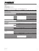
Electrical and Mechanical Characteristics, T
j
= 25°C unless otherwise specified
Characteristics Symbol Test Conditions Min. Typ. Max. Units
IGBT Inverter Sector
Collector-Emitter Saturation Voltage V
CE(sat)
V
D
= V
DB
= 15V, I
C
= 20A, V
IN
= 5V, T
j
= 25°C — 1.60 2.10 Volts
V
D
= V
DB
= 15V, I
C
= 20A, V
IN
= 5V, T
j
= 125°C — 1.70 2.20 Volts
Diode Forward Voltage V
EC
-I
C
= 20A, V
IN
= 0V — 1.50 2.00 Volts
Inductive Load Switching Times t
on
0.70 1.30 1.90 µS
t
rr
V
CC
= 300V, V
D
= V
DB
= 15V, — 0.30 — µS
t
C(on)
I
C
= 20A, T
j
= 125°C, — 0.50 0.80 µS
t
off
V
IN
= 0 – 5V, Inductive Load — 1.30 1.90 µS
t
C(off)
— 0.40 0.60 µS
Collector Cutoff Current I
CES
V
CE
= V
CES
, T
j
= 25°C — — 1.0 mA
V
CE
= V
CES
, T
j
= 125°C — — 10 mA
Control Sector
Circuit Current I
D
V
IN
= 5V Total of V
P1
-V
NC
, V
N1
-V
NC
— — 7.00 mA
V
D
= V
DB
= 15V V
UFB
-U, V
VFB
-V, V
WFB
-W — — 0.55 mA
V
IN
= 0V Total of V
P1
-V
NC
, V
N1
-V
NC
— — 7.00 mA
V
UFB
-V
UFS
, V
VFB
-V
VFS
, V
WFB
-V
WFS
— — 0.55 mA
Fault Output Voltage V
FOH
V
SC
= 0V, F
O
Terminal Pull-up to 5V by 10kΩ 4.9 — — Volts
V
FOL
V
SC
= 1V, I
FO
= 1mA — — 0.95 Volts
Short Circuit Trip Level* V
SC(ref)
V
D
= 15V 0.43 0.48 0.53 Volts
Input Current I
IN
V
IN
= 5V 1.0 1.5 2.0 mA
Supply Circuit Under-voltage UV
DBt
Trip Level, T
j
≤ 125°C 10.0 — 12.0 Volts
Protection UV
DBr
Reset Level, T
j
≤ 125°C 10.5 — 12.5 Volts
UV
Dt
Trip Level, T
j
≤ 125°C 10.3 — 12.5 Volts
UV
Dr
Reset Level, T
j
≤ 125°C 10.8 — 13.0 Volts
Fault Output Pulse Width** t
FO
C
FO
= 22nF 1.0 1.8 — ms
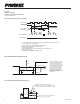
ON Threshold Voltage V
th(on)
Applied between — 2.3 2.6 Volts
OFF Threshold Voltage V
th(off)
U
P
, V
P
, W
P
-V
NC,
0.8 1.4 — Volts
ON/OFF Threshold Hysteresis Voltage V
th(hys)
U
N
, V
N
, W
N
-V
NC
0.5 0.9 — Volts
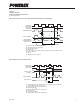
* Short Circuit protection is only for the lower-arms. Please select the external shunt resistance such that the S
C
trip level is less than 1.7 times the current rating.
**Fault signal is output when the low-arms short circuit or control supply under-voltage protective function works. The fault output pulse-width, t
FO
, depends on the capacitance of C
FO
according to the following approximate equation: C
FO
= 12.2 x 10
-6
x t
FO
[F].