
Instruction Manual
5
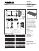
PS21267-P / PS21267-AP
Intellimod™ Module
Dual-In-Line Intelligent Power Module
30 Amperes/600 Volts
Powerex, Inc., 173 Pavilion Lane, Youngwood, Pennsylvania 15697 (724) 925-7272 www.pwrx.com
08/10 Rev. 01
Recommended Conditions for Use
Characteristic Symbol Condition Min. Typ. Max. Units
Supply Voltage V
CC
Applied between P-N 0 300 400 Volts
Control Supply Voltage V
D
Applied between V
P1
-V
PC
, V
N1
-V
NC
13.5 15.0 16.5 Volts
V
DB
Applied between 13.0 15.0 18.5 Volts
V
UFB
-V
UFS
,
V
VFB
-V
VFS
, V
WFB
-V
WFS
Control Supply Variation ΔV
D
, ΔV
DB
— -1 — 1 Volts/μs
PWM Input Frequency f
PWM
T
C
≤ 100°C, T
j
≤ 125°C — — 20 kHz
Allowable rms Current* I
O
V
CC
= 300V, V
D
= V
DB
= 15V, f
PWM
= 5kHz, — — 19.1 Arms
PF = 0.8, Sinusoidal, T
j
≤ 125°C, T
C
≤ 100°C
V
CC
= 300V, V
D
= V
DB
= 15V, f
PWM
= 15kHz, — — 11.6 Arms
PF = 0.8, Sinusoidal, T
j
≤ 125°C, T
f
≤ 100°C
Minimum Input P
WIN(on)
** — 0.3 — — µs
Pulse Width P
WIN(off)***
Below Rated Current 200 ≤ V
CC
≤ 350V, 1.5 — — µs
Between Rated Current 13.5 ≤ V
D
≤ 16.5V, 3.0 — — µs
& 1.7 Times of Rated Current 13.0 ≤ V
DB
≤ 18.5V,
Between 1.7 Times of Rated -20°C ≤ T
C
≤ 100°C, 3.6 — — µs
& 2.0 Times of Rated Current N-line Wiring Inductance Less Than 10nH
V
NC
Variation V
NC
Between V
NC
-N (Including Surge) -5.0 — 5.0 Volts
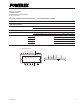
Arm Shoot-through t
DEAD
For Each Input Signal, T
C
< 100°C 2 — — µs
Blocking Time
* The allowable rms current value depends on the actual application conditions.
**If input signal ON pulse is less than P
WIN(on)
, the device may not respond.
***The IPM may fail to respond to an ON pulse if the preceeding OFF pulse is less than P
WIN(off)
.