
Instruction Manual
3
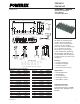
PS21267-P / PS21267-AP
Intellimod™ Module
Dual-In-Line Intelligent Power Module
30 Amperes/600 Volts
Powerex, Inc., 173 Pavilion Lane, Youngwood, Pennsylvania 15697 (724) 925-7272 www.pwrx.com
08/10 Rev. 01
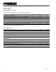
Electrical and Mechanical Characteristics, T
j
= 25°C unless otherwise specied
Characteristics Symbol Test Conditions Min. Typ. Max. Units
IGBT Inverter Sector
Collector-Emitter Cutoff Current I
CES
V
CE
= V
CES
, T
j
= 25°C — — 1.0 mA
V
CE
= V
CES
, T
j
= 125°C — — 10 mA
Diode Forward Voltage V
EC
T
j
= 25°C, -I
C
= 30A, V
IN
= 0V — 1.5 2.0 Volts
Collector-Emitter Saturation Voltage V
CE(sat)
I
C
= 30A, T
j
= 25°C, V
D
= V
DB
= 15V, V
IN
= 5V — 1.40 1.90 Volts
I
C
= 30A, T
j
= 125°C, V
D
= V
DB
= 15V, V
IN
= 5V — 1.40 1.90 Volts
Inductive Load Switching Times t
on
0.70 1.30 1.90 µs
t
rr
V
CC
= 300V, V
D
= V
DB
= 15V, — 0.30 — µs
t
C(on)
I
C
= 30A, T
j
= 125°C, V
IN
= 5 ⇔ 0V, — 0.40 0.60 µs
t
off
Inductive Load (Upper-Lower Arm) — 2.00 2.60 µs
t
C(off)
— 0.65 0.90 µs
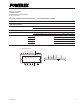
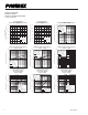
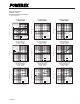
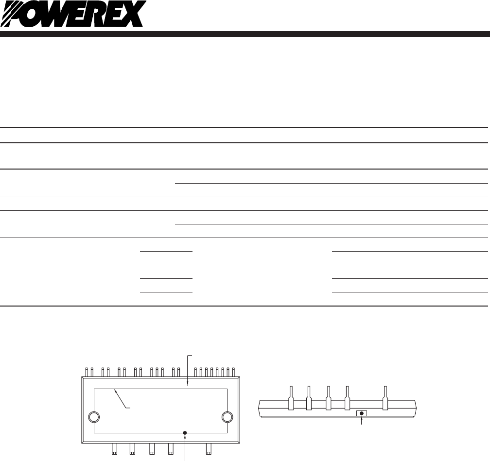
T
C
Measurement Point
T
T
C
T
C
HEATSINK BOUNDARY
POWER TERMINALS
CONTROL TERMINALS