
Manual


TENTATIVE
PP300D120
Powerex, Inc., 200 Hillis Street, Youngwood, Pennsylvania 15697-1800 (724) 925-7272
POW-R-PAK
TM
300A / 1200V
Half Bridge IGBT Assembly
PP300D120 (-) - 4 -
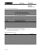
Gate Drive Board Interface Signal Definitions
Pin Signal Name Description
1 Shield Connected to circuit ground
2 PWM - 0-15 V signal controlling the duty cycle of - IGBT
3 Phase Error
1
Open collector output, external pull-up resistor required
LOW = No Error; Floating = Phase overcurrent or short circuit
4 PWM + 0-15 V signal controlling the duty cycle of + IGBT
5 Overtemp
1
Open collector output, external pull-up resistor required
LOW = No Error; Floating = heatsink overtemp
6 24 VDC input power
2
20 – 30 VDC input voltage range
7 24 VDC input power
2
20 – 30 VDC input voltage range
8 15 VDC input power
2
14.4 – 18 VDC input voltage range
9 15 VDC input power
2
14.4 – 18 VDC input voltage range
10 GND Ground reference for 15 and 24 VDC inputs
11 GND Ground reference for 15 and 24 VDC inputs
12 Heatsink Temperature Analog voltage representation of heatsink temperature
13 GND
3
Ground reference for analog signals
14 I
out
Analog voltage representation of output current
15
4
GND
3
Ground reference for analog signals
16
4
DC Link Voltage Analog voltage representation of DC link voltage
Notes:
1. Open collectors can be pulled up to 30 V max and sink 50mA continuous.
2. Do not connect a 15 VDC and 24 VDC source to the unit at the same time, use one or the other.
3. GND signals to be used for analog feedback signals, i.e. twisted pair with I
out
4. Optional outputs for DC link voltage feedback
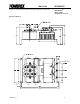
Gate Drive Board Interface Connector
Description Symbol Type Manufacturer
With DC Link Voltage Feedback Option
Gate Drive Board Interface Header J1 0.100” x 0.100” latching header, 16 pin 3M# 3408-6002 or equivalent
Recommended Mating Socket - 0.100” x 0.100” IDC socket, 16 pin 3M# 3452-7600 or equivalent
Recommended Strain Relief -
Plastic strain relief 3M# 3448-3014 or equivalent
Without DC Link Voltage Feedback Option
Gate Drive Board Interface Header J1 0.100” x 0.100” latching header, 14 pin 3M# 3314-6002 or equivalent
Recommended Mating Socket - 0.100” x 0.100” IDC socket, 14 pin 3M# 3385-7600 or equivalent
Recommended Strain Relief -
Plastic strain relief 3M# 3448-3014 or equivalent