
Instruction Manual


TENTATIVE
PP150B060
Powerex, Inc., 200 Hillis Street, Youngwood, Pennsylvania 15697-1800 (724) 925-7272
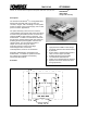
POW-R-PAK
TM
150A / 600V
H-Bridge IGBT Assembly
PP150B060(-) - 2 -
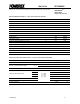
Absolute Maximum Ratings, T
j
= 25°C unless otherwise specified
General Symbol Units
IGBT Junction Temperature T
j
-40 to +150 °C
Storage Temperature T
stg
-40 to +125 °C
Operating Temperature T
op
-25 to +85 °C
Voltage Applied to DC terminals V
CC
400 Volts
Isolation Voltage, AC 1 minute, 60Hz sinusoidal V
iso
2500 Volts
IGBT Inverter
Collector Current (T
C
= 25°C) I
C
150 Amperes
Peak Collector Current (T
j
< 150°C) I
CM
300 Amperes
Emitter Current I
E
150 Amperes
Peak Emitter Current I
EM
300 Amperes
Maximum Collector Dissipation (T
j
< 150°C) P
c
520 Watts
Gate Drive Board
Unregulated +24V Power Supply 30 Volts
Regulated +15V Power Supply 18 Volts
PWM Signal Input Voltage 20 Volts
Fault Output Supply Voltage 30 Volts
Fault Output Current 50 mA
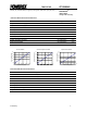
IGBT Inverter Electrical Characteristics, T
j
= 25°C unless otherwise specified
Characteristics Symbol Test Conditions Min Typ Max Units
Collector Cutoff Current I
CES
V
CE
= V
CES
, V
GE
= 0V - - 1 mA
I
C
= 150A, T
j
= 25°C - 1.6 2.2 Volts
Collector – Emitter Saturation Voltage V
CE(sat)
I
C
= 150A, T
j
= 125°C - 1.6 - Volts
Emitter – Collector Voltage V
EC
I
E
= 150A - - 2.6 Volts
t
d(on)
- - 120 ns
t
r
- - 100 ns
t
d(off)
- - 350 ns
Inductive Load Switching Times
t
f
- - 250 ns
Diode Reverse Recovery Time t
rr
- - 150 ns
Diode Reverse Recovery Charge Q
rr
V
CC
= 300V
I
C
= 150A
V
GE
= 15V
R
G
= 4.2Ω
- 2.8 - µC
DC Link Capacitance 18000 µF