
User Manual


Powerex, Inc., 200 Hillis Street, Youngwood, Pennsylvania 15697-1800 (724) 925-7272
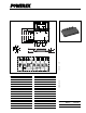
Intellimod™ Module
Three Phase + Brake
IGBT Inver ter Output
75 Amperes/600 Volts
PM75RSK060
549
Description:
Powerex Intellimod™ Intelligent
Power Modules are isolated base
modules designed for power
switching applications operating
at frequencies to 20kHz. Built-in
control circuits provide optimum
gate drive and protection for the
IGBT and free wheel diode
power devices.
Features:
□ Complete Output Power
Circuit
□ Gate Drive Circuit
□ Protection Logic
– Shor t Circuit
– Over Current
– Over Temperature
– Under Voltage
Applications:
□ Inverters
□ UPS
□ Motion/Servo Control
□ Power Supplies
Ordering Information:
Example: Select the complete
par t number from the table below
-i.e. PM75RSK060 is a 600V,
75 Ampere Intellimod™ Intelligent
Power Module.
Type Current Rating V
CES
Amperes Volts (x 10)
PM 75 60
1.
2.
3.
4.
5.
6.
7.
8.
9.
V
V
V
V
V
V
V
10.
11.
12.
13.
14.
15.
16.
U
UN
V
V
W
W
WPC
UPI
VPI
WPI
NC
NI
P
P
P
N
N
UPC
F
O
V
VPC
BM
17.
18.
19.
20.
21. B
R
N
U
V
P
22.
23.
24.
W25.
W
FO
O
V
F
O
U
F
V
VCC
SI
GND GND
OUT
UPI
V
U
FO
UP
UPC
F O
IN
V
CC
SI
GND GND
OUT
F
O
IN
V
CC
SI
GND GND
OUT
F
O
IN
V
V
FO
V
V
FO
VPI
V
VP
VPC
WPI
W
WP
WPC
VCC
SI
GND GND
OUT
F
O
IN
V
CC
SI
GND GND
OUT
F
O
IN
U
N
VCC
SI
GND GND
OUT
F
O
IN
V
V
W
N
V
NI
N
NC
TEMP
F
O
PUVWN
VCC
SI
GND GND
OUT
F
O
IN
B
R
fo
th
B
R
214365789 1210 11 13 1614 15 17 18 19
20 21 22 23 24 25
"T" (4 TYP)
TYP
M FF
N
C
Q
R
S
TYP
TYP
TYP
(4 PLACES)
A
E
W
F
G
H
B
D
JP
L
X
V
U
K
R"Y"
TAB DETAIL
BB
AA
Z
CC
U+2205EE
DD
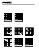
Dimensions Inches Millimeters
A 2.76±0.04 70.0±1.0
B 4.29±0.04 109.0±1.0
C 0.83±0.04 21.0±1.0
D 3.78±0.02 96.0±0.5
E 2.31±0.02 58.5±0.5
F 2.22±0.03 56.5±0.8
G 1.61 41.0
H 1.30 33.0
J 2.40±0.03 60.96±0.8
K 0.30 7.62
L 0.10±0.01 2.54±0.25
M 0.66 16.75
N 0.49±0.01 12.5±0.25
P 0.69 17.52
Q 0.53 13.5
Dimensions Inches Millimeters
R 0.21 5.4
S 0.39 10.0
T 0.18 4.5
U 0.02 0.6
V 0.02 0.4
W 0.03 0.75
X 0.03 0.8
Y 0.20 5.0
Z 0.25 6.35
AA 0.04 1.0
BB 0.39 9.95
CC 0.24 6.0
DD 0.21 5.4
EE 0.07 1.65
FF 2.46±0.03 62.5±0.08
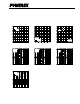
Outline Drawing and Circuit Diagram