
User Manual
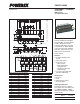

PM50CL1A060
Intellimod™ L1-Series
Three Phase IGBT Inverter
50 Amperes/600 Volts
2
Powerex, Inc., 173 Pavilion Lane, Youngwood, Pennsylvania 15697 (724) 925-7272 www.pwrx.com
03/10 Rev. 1
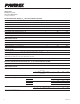
Absolute Maximum Ratings, T
j
= 25°C unless otherwise specied
Characteristics Symbol PM50CL1A060 Units
Power Device Junction Temperature T
j
-20 to 150 °C
Storage Temperature T
stg
-40 to 125 °C
Mounting Torque, M5 Mounting Screws — 31 in-lb
Mounting Torque, M5 Main Terminal Screws — 31 in-lb
Module Weight (Typical) — 380 Grams
Supply Voltage, Surge (Applied between P - N) V
CC(surge)
500 Volts
Supply Voltage Protected by Short Circuit Protection Capability* V
CC(prot.)
400 Volts
Isolation Voltage, AC 1 minute, 60Hz Sinusoidal V
ISO
2500 Volts
IGBT Inverter Sector
Collector-Emitter Voltage (V
D
= 15V, V
CIN
= 15V) V
CES
600 Volts
Collector Current (T
C
= 25°C) (Note 1) ±I
C
50 Amperes
Peak Collector Current (T
C
= 25°C) ±I
CP
100 Amperes
Collector Dissipation (T
C
= 25°C) (Note 1) P
C
284 Watts
Control Sector
Supply Voltage (Applied between V
UP1
-V
UPC
, V
VP1
-V
VPC
, V
WP1
-V
WPC
, V
N1
-V
NC
) V
D
20 Volts
Input Voltage (Applied between U
P
-V
UPC
, V
P
-V
VPC
, W
P
-V
WPC
, U
N
- V
N
- W
N
-V
NC
) V
CIN
20 Volts
Fault Output Supply Voltage V
FO
20 Volts
(Applied between U
FO
-V
UPC
, V
FO
-V
VPC
, W
FO
-V
WPC
, F
O
-V
NC
)
Fault Output Current (Sink Current at U
FO
, V
FO
, W
FO
, F
O
Terminals) I
FO
20 mA
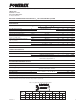
Electrical and Mechanical Characteristics, T
j
= 25°C unless otherwise specied
Characteristics Symbol Test Conditions Min. Typ. Max. Units
IGBT Inverter Sector
Collector-Emitter Saturation Voltage V
CE(sat)
V
D
= 15V, V
CIN
= 0V, I
C
= 50A, — 1.75 2.35 Volts
T
j
= 25°C
V
D
= 15V, V
CIN
= 0V, I
C
= 50A, — 1.75 2.35 Volts
T
j
= 125°C
Diode Forward Voltage V
EC
-I
C
= 50A, V
CIN
= 15V, V
D
= 15V — 1.7 2.8 Volts
Inductive Load Switching Times t
on
0.3 0.8 2.0 µs
t
rr
V
D
= 15V, V
CIN
= 0 ↔ 15V — 0.4 0.8 µs
t
C(on)
V
CC
= 300V, I
C
= 50A — 0.4 1.0 µs
t
off
T
j
= 125°C — 1.0 2.3 µs
t
C(off)
— 0.3 1.0 µs
Collector-Emitter Cutoff Current I
CES
V
CE
= V
CES
, V
D
= 15V, T
j
= 25°C — — 1.0 mA
V
CE
= V
CES
, V
D
= 15V, T
j
= 125°C — — 10 mA
*VD = 13.5 ~ 16.5V, Inverter Part, T
j
= 125°C