
Owner's manual
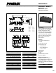

PM400DVA060
Intellimod™ Module
Single Phase IGBT Inverter Output
400 Amperes/600 Volts
410
Powerex, Inc., 200 Hillis Street, Youngwood, Pennsylvania 15697-1800 (724) 925-7272
Electrical and Mechanical Characteristics, T
j
= 25°C unless otherwise specified
Characteristics Symbol Test Conditions Min. Typ. Max. Units
IGBT Inverter Sector
Collector-Emitter Cutoff Current I
CES
V
CE
= V
CES
, V
D
= 15V, T
j
= 25°C — — 1.0 mA
V
CE
= V
CES
, V
D
= 15V, T
j
= 125°C — — 10.0 mA
FWDi Forward Voltage V
EC
-I
C
= 400A, V
D
= 15V, V
CIN
= 5V — 2.20 3.30 Volts
Collector-Emitter Saturation Voltage V
CE(sat)
V
D
= 15V, V
CIN
= 0V, I
C
= 400A, — 2.35 2.80 Volts
Pulsed, T
j
= 25°C
V
D
= 15V, V
CIN
= 0V, I
C
= 400A, — 2.55 3.05 Volts
Pulsed, T
j
= 125°C
Inductive Load Switching Times t
on
0.5 1.4 2.5 µS
t
rr
V
D
= 15V, V
CIN
= 0 ~ 5V — 0.15 0.3 µS
t
C(on)
V
CC
= 300V, I
C
= 400A, — 0.4 1.0 µS
t
off
T
j
= 125°C — 2.0 3.0 µS
t
C(off)
— 0.5 1.0 µS
Thermal Characteristics
Characteristic Symbol Condition Min. Typ. Max. Units
Junction to Case Thermal Resistance R
th(j-c)Q
Each Inverter IGBT — — 0.11 °C/Watt
R
th(j-c)D
Each Inverter FWDi — — 0.18 °C/Watt
Contact Thermal Resistance R
th(c-f)
Case to Fin Per Module, — — 0.081 °C/Watt
Thermal Grease Applied
Recommended Conditions for Use
Characteristic Symbol Condition Value Units
Supply Voltage V
CC
Applied across C1-E2 Terminals ≤ 400 Volts
V
CE(surge)
Applied across C1-E1, C2-E2 Terminals ≤ 500 Volts
V
D
Applied between 15 ± 1.5 Volts
V
P1
-V
PC
, V
N1
-V
NC *
Input ON Voltage V
CIN(on)
Applied between ≤ 0.8 Volts
Input OFF Voltage V
CIN(off)
C
P1
-V
PC
, C
N1
-V
NC
≥ 4.0 Volts
Arm Shoot-Through Blocking Time t
DEAD
For IPM's each Input Signal ≥ 3.5 µS
* With ripple satisfying the following conditions, dv/dt swing ≤ 5V/µs, Variation ≤ 2V peak to peak.