
User Manual


3
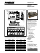
PM300RLA060
Intellimod™ L-Series
Three Phase IGBT Inverter + Brake
300 Amperes/600 Volts
Powerex, Inc., 200 E. Hillis Street, Youngwood, Pennsylvania 15697-1800 (724) 925-7272
Electrical and Mechanical Characteristics, T
j
= 25°C unless otherwise specified
Characteristics Symbol Test Conditions Min. Typ. Max. Units
IGBT Inverter Sector
Collector-Emitter Cutoff Current I
CES
V
CE
= V
CES
, V
D
= 15V, T
j
= 25°C — — 1.0 mA
V
CE
= V
CES
, V
D
= 15V, T
j
= 125°C — — 10 mA
Diode Forward Voltage V
EC
-I
C
= 300A, V
CIN
= 15V, V
D
= 15V — 2.2 3.3 Volts
Collector-Emitter Saturation Voltage V
CE(sat)
V
D
= 15V, V
CIN
= 0V, I
C
= 300A, — 1.6 2.1 Volts
T
j
= 25°C
V
D
= 15V, V
CIN
= 0V, I
C
= 300A, — 1.5 2.0 Volts
T
j
= 125°C
Inductive Load Switching Times t
on
0.5 1.0 2.4 µs
t
rr
V
D
= 15V, V
CIN
= 0 ⇔ 15V — 0.2 0.4 µs
t
C(on)
V
CC
= 300V, I
C
= 300A — 0.4 1.0 µs
t
off
T
j
= 125°C — 1.2 2.5 µs
t
C(off)
— 0.5 1.0 µs
IGBT Brake Sector
Collector-Emitter Cutoff Current I
CES
V
CE
= V
CES
, V
D
= 15V, T
j
= 25°C — — 1.0 mA
V
CE
= V
CES
, V
D
= 15V, T
j
= 125°C — — 10 mA
Diode Forward Voltage V
FM
I
F
= 150A — 2.2 3.3 Volts
Collector-Emitter Saturation Voltage V
CE(sat)
V
D
= 15V, V
CIN
= 0V, I
C
= 150A, — 1.6 2.1 Volts
T
j
= 25°C
V
D
= 15V, V
CIN
= 0V, I
C
= 150A, — 1.5 2.0 Volts
T
j
= 125°C
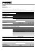
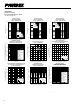
Note 1:T
C
(Base Plate) Measurement Point
TOP VIEW
T
C
MEASUREMENT
POINT