6121 Baker Road, Suite 108 Minnetonka, MN 55345 Phone (952) 933-6190 Fax (952) 933-6223 1-800-274-4284 www.chtechnology.com Thank you for downloading this document from C&H Technology, Inc. Please contact the C&H Technology team for the following questions - Technical Application Assembly Availability Pricing Phone – 1-800-274-4284 E-Mail – sales@chtechnology.com www.chtechnology.com - SPECIALISTS IN POWER ELECTRONIC COMPONENTS AND ASSEMBLIES - www.chtechnology.
PM25RLB120 Powerex, Inc., 200 E.
Powerex, Inc., 200 E.
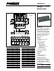
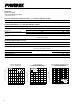
Powerex, Inc., 200 E. Hillis Street, Youngwood, Pennsylvania 15697-1800 (724) 925-7272 PM25RLB120 Intellimod™ L-Series Three Phase IGBT Inverter + Brake 25 Amperes/1200 Volts Electrical and Mechanical Characteristics, Tj = 25°C unless otherwise specified Characteristics Symbol Test Conditions Min. Typ. Max. Units IGBT Inverter Sector Collector-Emitter Cutoff Current Diode Forward Voltage Collector-Emitter Saturation Voltage ICES VCE = VCES, VD = 15V, Tj = 25°C — — 1.
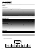
Powerex, Inc., 200 E. Hillis Street, Youngwood, Pennsylvania 15697-1800 (724) 925-7272 PM25RLB120 Intellimod™ L-Series Three Phase IGBT Inverter + Brake 25 Amperes/1200 Volts Electrical and Mechanical Characteristics, Tj = 25°C unless otherwise specified Characteristics Symbol Test Conditions Min. Typ. Max. Units Thermal Characteristics, Tj = 25°C unless otherwise specified Characteristic Symbol Condition Min. Typ. Max.
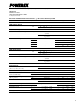
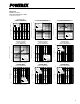
Powerex, Inc., 200 E. Hillis Street, Youngwood, Pennsylvania 15697-1800 (724) 925-7272 PM25RLB120 Intellimod™ L-Series Three Phase IGBT Inverter + Brake 25 Amperes/1200 Volts FREE-WHEEL DIODE FORWARD CHARACTERISTICS (TYPICAL - INVERTER PART) VD = 15V Tj = 25°C Tj = 125°C 101 0 0.5 1.0 1.5 2.0 2.5 100 100 101 10-1 VCC = 600V VD = 15V Tj = 25°C Tj = 125°C INDUCTIVE LOAD 10-2 100 102 101 COLLECTOR CURRENT, -IC, (AMPERES) COLLECTOR CURRENT, -IC, (AMPERES) SWITCHING LOSS (ON) VS.
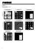
Powerex, Inc., 200 E. Hillis Street, Youngwood, Pennsylvania 15697-1800 (724) 925-7272 CIRCUIT CURRENT VS. FREQUENCY CHARACTERISTICS (TYPICAL ) REVERSE RECOVERY SWITCHING LOSS VS. COLLECTOR CURRENT (TYPICAL - INVERTER PART) 101 50 100 VD = 15V Tj = 25°C 40 CIRCUIT CUTTENT, ID, (mA) REVERSE RECOVERY SWITCHING LOSS, Err, (mJ/PULSE) VCC = 600V VD = 15V Tj = 25°C Tj = 125°C INDUCTIVE LOAD 30 N-SIDE 20 100 0 10 15 25 10-3 10-3 10-2 10-1 100 2.0 0.5 1.0 1.5 2.0 1.5 1.0 0.5 0 2.