
User Manual

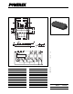


PM20CSJ060
Intellimod™ Module
Three Phase IGBT Inverter Output
20 Amperes/600 Volts
472
Powerex, Inc., 200 Hillis Street, Youngwood, Pennsylvania 15697-1800 (724) 925-7272
Electrical and Mechanical Characteristics, T
j
= 25°C unless otherwise specified
Characteristics Symbol Test Conditions Min. Typ. Max. Units
IGBT Inverter Sector
Collector Cutoff Current I
CEX
V
CE
= V
CEX
, T
j
= 25°C — — 1.0 mA
V
CE
= V
CEX
, T
j
= 125°C——10mA
Diode Forward Voltage V
FM
-I
C
= 20A, V
D
= 15V, V
CIN
= 15V — 2.5 3.5 Volts
Collector-Emitter Saturation Voltage V
CE(sat)
V
D
= 15V, V
CIN
= 0V, I
C
= 20A — 1.8 2.5 Volts
V
D
= 15V, V
CIN
= 0V, I
C
= 20A, — 1.9 2.6 Volts
T
j
= 125°C
Inductive Load Switching Times t
on
0.3 0.5 1.5 µS
t
rr
V
D
= 15V, V
CIN
= 0 ~ 15V — 0.12 0.3 µS
t
C(on)
V
CC
= 300V, I
C
= 20A — 0.2 0.8 µS
t
off
T
j
= 125°C — 1.5 2.3 µS
t
C(off)
— 0.5 1.5 µS
Thermal Characteristics
Characteristic Symbol Condition Min. Typ. Max. Units
Junction to Case Thermal Resistance R
th(j-c)Q
Each IGBT — — 2.2 °C/Watt
R
th(j-c)D
Each FWDi — — 4.5 °C/Watt
Contact Thermal Resistance R
th(c-f)
Case to Fin Per Module, — — 0.083 °C/Watt
Thermal Grease Applied
Recommended Conditions for Use
Characteristic Symbol Condition Value Units
Supply Voltage V
CC
Applied across P-N Terminals 0 ~ 400 Volts
V
D
Applied between V
UP1
-V
UPC
, 15 ± 1.5 Volts
V
N1
-V
NC
, V
VP1
-V
VPC
, V
WP1
-V
WPC
Input ON Voltage V
CIN(on)
Applied between 0 ~ 0.8 Volts
Input OFF Voltage V
CIN(off)
U
P
, V
P
, W
P
, U
N,
V
N,
W
N
4.0 ~ V
D
Volts
PWM Input Frequency f
PWM
Using Application Circuit 5 ~ 20 kHz
Minimum Dead Time t
DEAD
Input Signal ≥ 2.0 µS