
Owner manual

5
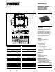
PM200RSD060
Intellimod™ Module
Three Phase + Brake IGBT Inverter Output
200 Amperes/600 Volts
Powerex, Inc., 200 Hillis Street, Youngwood, Pennsylvania 15697-1800 (724) 925-7272
Thermal Characteristics
Characteristic Symbol Condition Min. Typ. Max. Units
Junction to Case Thermal Resistance R
th(j-c)Q
Each IGBT — — 0.21 °C/Watt
Inverter Part R
th(j-c)F
Each FWDi — — 0.35 °C/Watt
R
th(j-c´)Q
Each IGBT* — — 0.13** °C/Watt
R
th(j-c´)F
Each FWDi* — — 0.21** °C/Watt
Junction to Case Thermal Resistance R
th(j-c)Q
Each IGBT — — 0.40 °C/Watt
Brake Part R
th(j-c)F
Each FWDi — — 1.10 °C/Watt
R
th(j-c´)Q
Each IGBT* — — 0.27** °C/Watt
R
th(j-c´)F
Each FWDi* — — 0.47** °C/Watt
Contact Thermal Resistance R
th(c-f)
Case to Fin Per Module, — — 0.018 °C/Watt
Thermal Grease Applied
*T
C
measured point is just under chip.
**If you use this value, R
th(f-a)
should be measured just under the chips.
Recommended Conditions for Use
Characteristic Symbol Condition Value Units
Supply Voltage V
CC
Applied across P-N Terminals 0 ~ 400 Volts
Control Supply Voltage*** V
D
Applied between V
UP1
-V
UPC
, 15 ± 1.5 Volts
V
N1
-V
NC
, V
VP1
-V
VPC
, V
WP1
-V
WPC
Input ON Voltage V
CIN(on)
Applied between 0 ~ 0.8 Volts
Input OFF Voltage V
CIN(off)
U
P
, V
P
, W
P
, U
N,
V
N,
W
N,
B
r
-V
NC
4.0 ~ V
D
Volts
PWM Input Frequency f
PWM
Using Application Circuit 5 ~ 20 kHz
Minimum Dead Time t
DEAD
Input Signal ≥ 2.0 µS
I
F
= 12mA ≥ 2.5 µS
*** With ripple satisfying the following conditions: dv/dt swing ≤ ±5V/µs, Variation ≤ 2V peak to peak.