
Instruction Manual

PM150RL1A060
Intellimod™ L1-Series
Three Phase IGBT Inverter + Brake
150 Amperes/600 Volts
2
Powerex, Inc., 173 Pavilion Lane, Youngwood, Pennsylvania 15697 (724) 925-7272 www.pwrx.com
03/10 Rev. 1
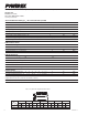
Absolute Maximum Ratings, T
j
= 25°C unless otherwise specied
Characteristics Symbol PM150RL1A060 Units
Power Device Junction Temperature T
j
-20 to 150 °C
Storage Temperature T
stg
-40 to 125 °C
Mounting Torque, M5 Mounting Screws — 31 in-lb
Mounting Torque, M5 Main Terminal Screws — 31 in-lb
Module Weight (Typical) — 380 Grams
Supply Voltage, Surge (Applied between P - N) V
CC(surge)
500 Volts
Self-protection Supply Voltage Limit (Short Circuit protection Capability)* V
CC(prot.)
400 Volts
Isolation Voltage, AC 1 minute, 60Hz Sinusoidal V
ISO
2500 Volts
IGBT Inverter Sector
Collector-Emitter Voltage (V
D
= 15V, V
CIN
= 15V) V
CES
600 Volts
Collector Current (T
C
= 25°C) (Note 1) ±I
C
150 Amperes
Peak Collector Current (T
C
= 25°C) ±I
CP
300 Amperes
Collector Dissipation (T
C
= 25°C) (Note 1) P
C
500 Watts
IGBT Brake Sector
Collector-Emitter Voltage (V
D
= 15V, V
CIN
= 15V) V
CES
600 Volts
Collector Current (T
C
= 25°C) (Note 1) ±I
C
75 Amperes
Peak Collector Current (T
C
= 25°C) ±I
CP
150 Amperes
Collector Dissipation (T
C
= 25°C) (Note 1) P
C
328 Watts
Diode Forward Current I
F
75 Amperes
Diode Rated DC Reverse Voltage (T
C
= 25°C) V
R(DC)
600 Volts
Control Sector
Supply Voltage (Applied between V
UP1
-V
UPC
, V
VP1
-V
VPC
, V
WP1
-V
WPC
, V
N1
-V
NC
) V
D
20 Volts
Input Voltage (Applied between U
P
-V
UPC
, V
P
-V
VPC
, W
P
-V
WPC
, U
N
- V
N
- W
N
-Br-V
NC
) V
CIN
20 Volts
Fault Output Supply Voltage V
FO
20 Volts
(Applied between U
FO
-V
UPC
, V
FO
-V
VPC
, W
FO
-V
WPC
, F
O
-V
NC
)
Fault Output Current (U
FO
, V
FO
, W
FO
, F
O
Terminals) I
FO
20 mA
*VD = 13.5 ~ 16.5V, Inverter Part, T
j
= 125°C
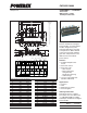
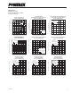
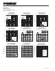
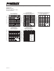
Arm UP VP WP UN VN WN Br
Axis IGBT FWDi IGBT FWDi IGBT FWDi IGBT FWDi IGBT FWDi IGBT FWDi IGBT FWDi
X 27.8 27.8 65.5 65.5 87.5 87.5 38.8 38.8 54.5 54.5 76.5 76.5 17.7 18.5
Y -8.4 -1.6 -8.4 -0.2 -8.4 -0.2 8.0 -0.4 8.0 -0.4 8.0 -0.4 -10.2 4.0
Note 1: T
C
(under the chip) Measurement Point
Y
BOTTOM VIEW
X