
User Manual

www.vishay.com For technical questions, contact: indmodules@vishay.com
Document Number: 93754
4 Revision: 04-Nov-09
P100 Series
Vishay High Power Products
Passivated Assembled
Circuit Elements, 25 A
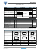
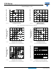
Fig. 1 - Current Ratings Nomogram (1 Module Per Heatsink)
Fig. 2 - On-State Power Loss Characteristics
Fig. 3 - On-State Power Loss Characteristics
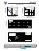
Fig. 4 - Current Ratings Characteristics
Fig. 5 - On-State Voltage Drop Characteristics
Maximum Total Power Loss (W)
Total Output Current (A)
5101520
25
0
0
60
50
40
30
20
10
93754_01a
~
+
-
180°
(sine)
T
J
= 125 °C
Maximum Total Power Loss (W)
Maximum Allowable
Ambient Temperature (°C)
25 7550 100 125
0
60
50
40
30
20
10
0
93754_01b
R
thSA
= 15 K/W - ΔR
2 K/W
3 K/W
7 K/W
10 K/W
5 K/W
Maximum Average On-State
Power Loss (W)
Average On-State Current (A)
10 1505
15
10
5
0
93754_02
180°
120°
90°
60°
30°
RMS limit
Ø
Conduction angle
T
J
= 125 °C
Per junction
Maximum Average On-State
Power Loss (W)
Average On-State Current (A)
20010155
20
10
15
5
0
93754_03
DC
180°
120°
90°
60°
30°
RMS limit
T
J
= 125 °C
Per junction
Conduction period
Ø
Maximum Allowable Case
Temperature (°C)
Total Output Current (A)
10 2051525
30
0
70
80
90
100
110
120
130
93754_04
180°
(Sine)
180°
(Rect.)
Fully turned-on
Per module
Instantaneous On-State Current (A)
Instantaneous On-State Voltage (V)
0123456
1
100
10
1000
93754_05
T
J
= 25 °C
T
J
= 125 °C
Per junction